
This guide provides a standardized procedure for configuring radar parameters to ensure accurate vehicle tracking and speed measurement for models: TSxxxx-VPC, TSxxxx-VPE, TSxxxx-VPG1, and TS5510-GVH.
1. About Milesight Radar AI LPR Camera
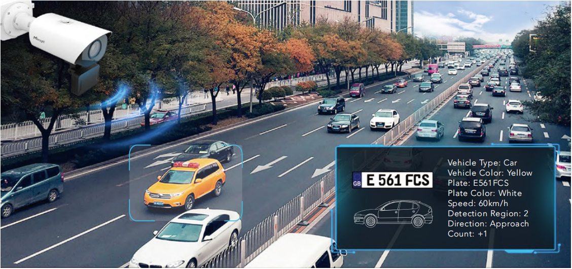
Milesight innovatively combines 3D Radar, AI, and LPR technologies to create a camera that can identify vehicles and read plates accurately and precisely, providing extra real-time data on vehicle position, direction, speed, etc. The all-in-one Radar AI LPR camera is easy to install as the 3D radar module is already integrated into the camera directly, realizing the hassle-free traffic flow monitoring solution.
2. Installation Considerations
To increase the accuracy of license plate recognition and Radar detection, be sure to install the Radar LPR cameras properly to capture the license plates with the correct image size, lighting conditions and camera angle. The following highlights are the tips for camera installation:
Recommended installing the camera in front of the vehicle:
It is recommended to mount the camera on a gantry or mounting bracket to ensure the camera captures the full view of the vehicle.
Notes:
It is recommended that the camera be installed on a straight section to ensure that the device can read the license plate head-on to ensure accurate recognition. For more radar installation details, please refer to the linked video. (https://www.youtube.com/watch?v=u88gNAdrJnM)
Recommended installation height:
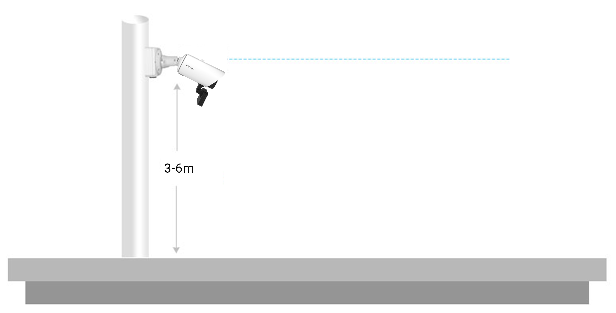
To avoid capturing unnecessary content in the image, the Radar AI LPR camera should be installed in a higher position, and the recommended installation height of the camera (from the ground) is from 3 to 6 meters.
Recommended installation angle:
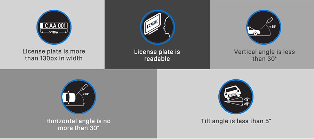
Install the camera at a suitable angle (Vertical angle is less than 30°; Horizontal angle is no more than 30°; Tilt angle is less than 5°) to capture the front of the vehicle.
Instructions for use of radar module:
①:The radar board is used to transmit and receive radar waves, and the angle can be adjusted. We recommend that you keeping it vertical to the horizontal field of view of the camera when using it. The recommended radar board adjustment angle range is 0-15°;
②: The detection range of the radar module is a vertical angle of 17°, left and right 56°.
Keep the detection range of the radar board unobstructed and cover the detection target;
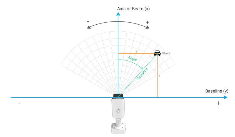
③: Detection distance of the radar module is up to 90m. Please ensure that the detection target is within the detection range.
Notes:
In order to ensure the stable use and high accuracy of the radar detection function, you need to pay attention to:
①:Keep away from other signal antennas when installing;
②:The surface of the radar antenna should be kept as flat as possible to avoid scratches. Any slight bend will have a significant on the detection result;
③:The radar module must be fully protected against static electricity during transportation, storage, use, and handling.
Detection performance of radar module:
Milesight Radar AI LPR Camera uses 60GHz millimeter wave radar, which is a medium-range radar. It can detect target distance, speed, and angle information by receiving radar reflections.
Function | Description |
Capture Rate | >99% (Traffic jam >95%) |
Lane Coverage | 2 Lanes (Recognition ≥95% individually) |
Tracking Target | Up to 32 |
Speed Detection Range | ±5km/h~±120km/h |
Speed Detection Accuracy | ±0.36km/h |
Detection Distance Range | Up to 90m |
Distance Detection Accuracy | ±0.4m |
Angle Measurement Accuracy | ±0.5° |
Installation Height | 2-7m |
After successfully installing the camera, you must set the necessary web page configurations to use the Radar AI LPR-related functions.For the relevant settings of the LPR function, please refer to : How to Set ANPR Solution
The following steps are appropriate settings for the application of Radar technology.
3. How to Set Radar AI LPR Camera
The following introduction is based on the LPR version: T_61.8.0.5_AP. Devices can be updated to the latest version prior to setup. Firmware Download|The Latest Innovation|Milesight
3.1 Initial Setup of LPR and Radar Parameters
Step1: Adjust the Zoom length of the lens.
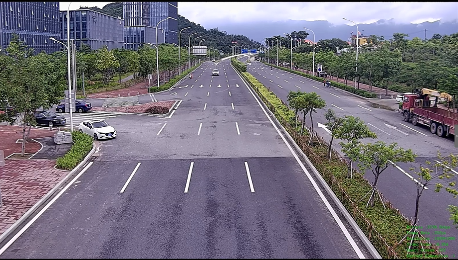
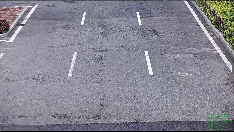
It is recommended to adjust the zoom length to cover the road range to be detected, as shown below.
|
|
Step2: Configure LPR General Settings.
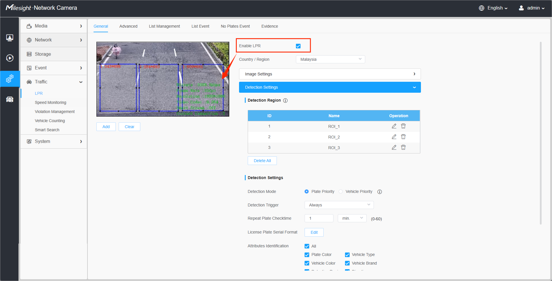
After logging in to the web, go to “Traffic”→ “LPR”→ “General”.
Check the checkbox “Enable LPR”, and the LPR detection areas can be drawn on the screen, which is shown in the blue box as below.
Please draw the LPR detection areas that match the number of lanes. For more information about the detection areas, please refer to .
Notes:
① It is recommended that the LPR area be drawn more than 30 meters from The Radar AI LPR Camera. Do not place the detection area too large to avoid the situation where it can contain multiple vehicles in front and behind;
② Complete other LPR related settings.For the relevant settings of the LPR function, please refer to the User Manual for operation. The following focus steps on the relevant settings for the application of Radar technology;
③ If you do not need to use the radar function, please turn off the radar function so as not to affect the detection of LPR.
Step3: Enable Radar Configuration.
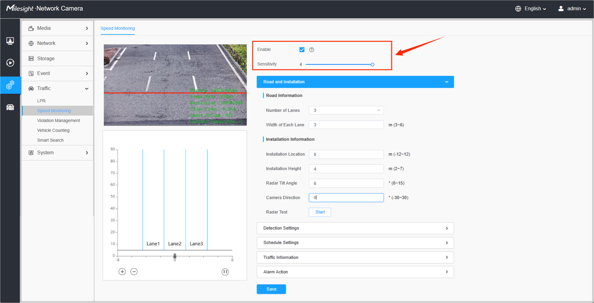
Go to the “Traffic”→ “Radar Configuration“,and check the checkbox to enable Radar Configuration.
Then, adjust the detection sensitivity of the radar module; level 1~4 is available. The easier the target is to be detected. Users can adjust the detection sensitivity as needed to avoid some missing or false detection, such as false detection caused by rain hitting the radar board.
Notes:
For users using the Radar AI LPR Camera for the first time, we recommend clicking the icon on the right to get the quick start guide.
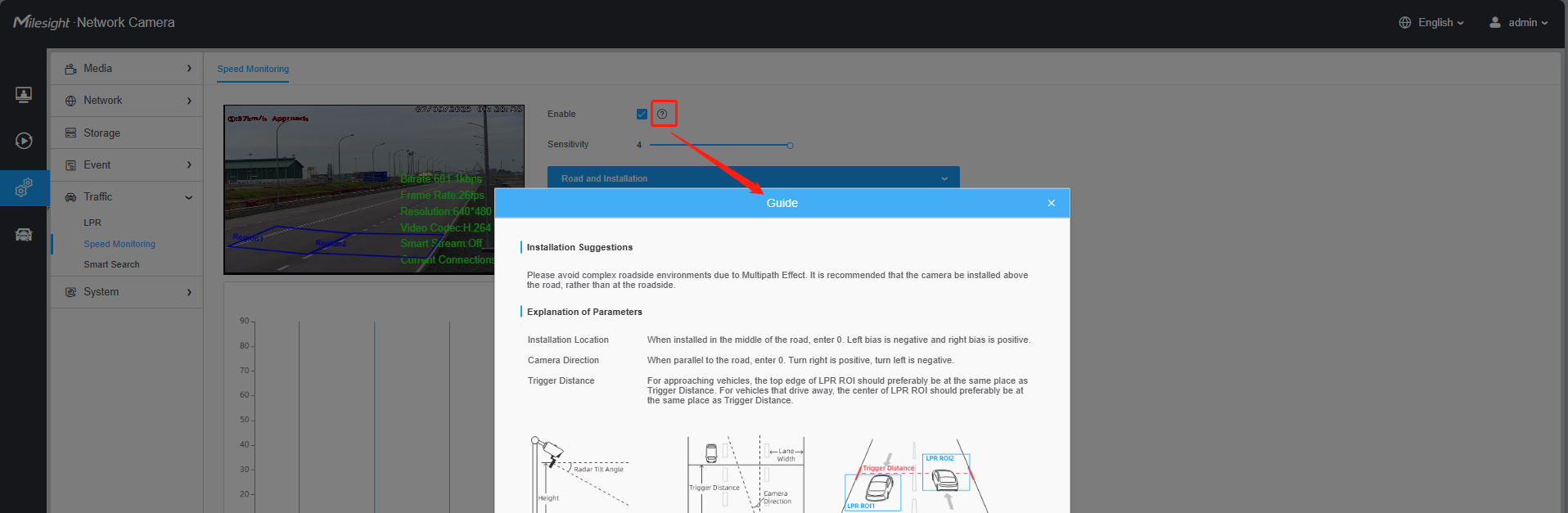
Step4: Fill in the road and installation information as shown below.
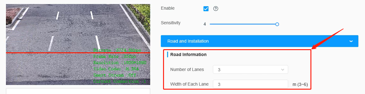
[Number of Lanes] & [Width of Each Lane]: Please fill in the number of lanes and the width of each lane according to the actual scene. It supports up to 4 lanes, and the width range of each lane is from 3 to 6 meters.
After setting the width of each lane, the radar detection range will be limited to the set range, and only the data within this range will be filtered out.
For example, the scene as shown below includes three lanes, each 3 meters wide.
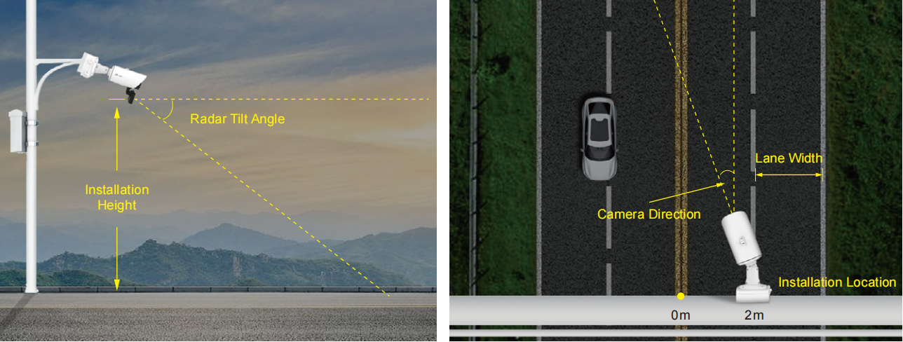
[Installation Location]: Please fill in the installation position of the camera on the road. The range is -12 to 12 meters, and the default is 0.
If the camera is installed in the middle of the road, fill in 0, otherwise, fill in the corresponding offset distance. It should be noted that the installation position needs to be confirmed as a positive or negative number. With the center of the road as the zero point, if the camera is installed on the left side of the road, it is defined as a negative number, and if it is on the right side, it is defined as a positive number.
[Installation Height]: Please fill in the installation height according to the actual installation height of the camera, and the range is 2 to 7 meters.
[Radar Tilt Angle]: Please fill in the Radar Tilt Angle according to the actual installation angle between the camera's field of view and the horizontal. The adjustable range of radar angle is 0-15°.
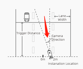
[Camera Direction]: Please fill in the angle between the direction of the camera installation and the road; the angel range is -30°~30°, and the default is 0°.
When the camera is parallel to the road, enter 0. Turn right is positive, and turn left is negative, as shown below.
[Radar Test]: After completing the above configuration, you can click the test button. Then, the above configuration will be automatically saved, and the radar module will start to test with the maximum sensitivity and maximum detection range,which is not limited by the lane configuration. In this way, the user can flexibly adjust the configuration according to the position of the target in the coordinates to achieve the most matching configuration.
|
|
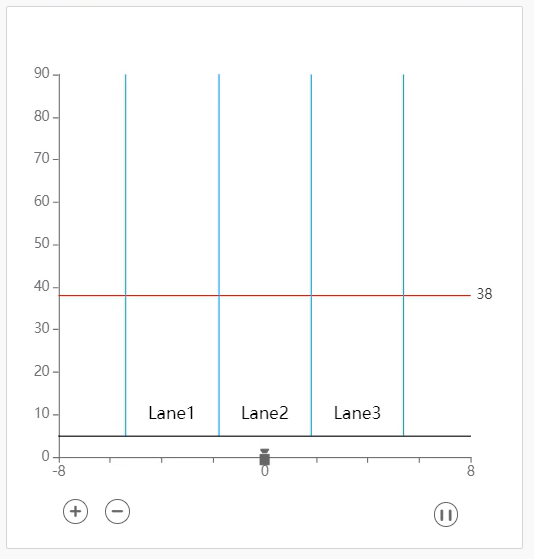
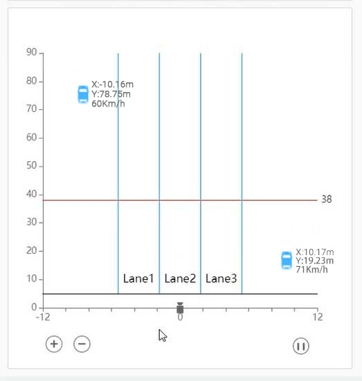
Note:
After 30 seconds of testing, the radar test function will be automatically turned off to prevent customers from forgetting to turn off the function.
3.2 Adjustment of Radar Parameters
Step1: Initialize Lane Detection Range
To ensure full coverage of the monitoring area, start by maximizing the detection field.
1. Navigate to the Radar Configuration interface and open the Road Information tab.
2. Set the Number of Lanes to 4 (Maximum) to cover all potential traffic areas.
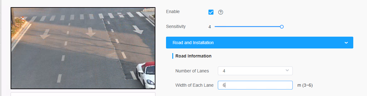
3. Set the Lane Width to its maximum value. This provides the widest possible field of view for initial calibration.
4. Monitor the Radar Trajectory Plot (bottom-left corner).
(1) Success: Real-time target tracks appear as vehicles pass.
(2) Failure: If no data appears, physically adjust the radar board orientation or the device tilt until the plot displays active tracking data.
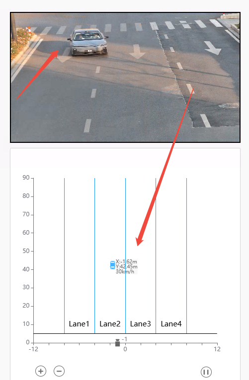
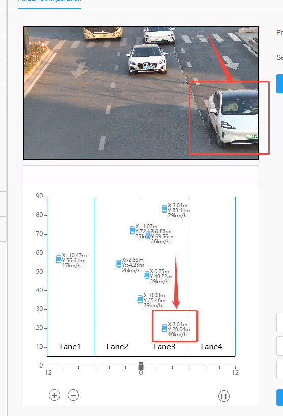
Step2: Align Trajectory Perpendicular to X-Axis
For accurate speed calculation, vehicle trajectories must be orthogonal (at a 90° angle) to the radar's horizontal baseline.
1. Observe the movement of targets (vehicles) on the Radar Trajectory Plot.
2. If the tracks are slanted (not vertical), go to the Camera Direction settings.
3. Fine-tune the Camera Direction parameter based on the slant:
• Trajectory tilts Left: Increase the parameter value.
• Trajectory tilts Right: Decrease the parameter value.
4. Continue adjusting until the trajectory lines are strictly perpendicular to the X-axis.
Note: Proper vertical alignment is the foundation for accurate lane assignment and velocity calculation.
Step3: Match Virtual Lanes to Physical Road
Once the data flow is straight, map the virtual configuration to the actual road layout.
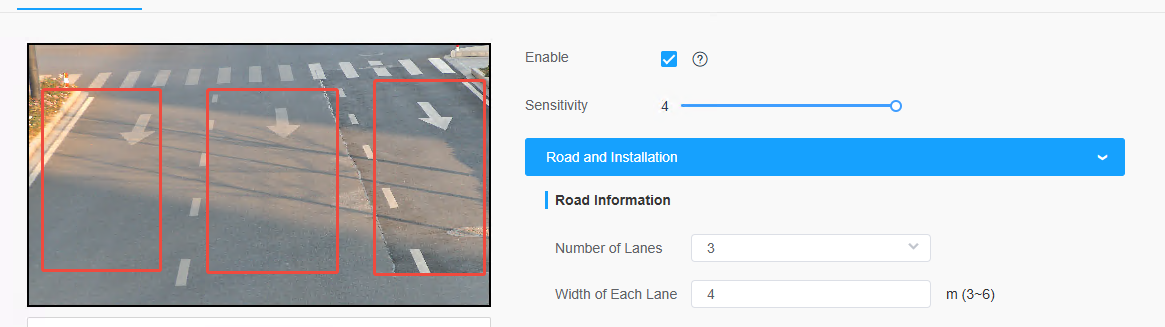
1. Set Lane Count
Adjust the Lane Number to match the actual number of lanes on the road.
2. Set Lane Width
Enter the actual Lane Width (e.g., 3.5m or 3.75m) for each lane.
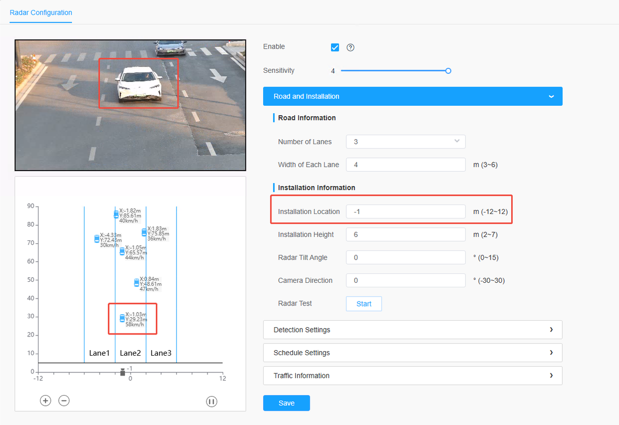
3. Calibrate Position
Use the Install Location setting to shift the entire trajectory group along the X-axis:
• Tracks are too far Left: Increase the parameter value.
• Tracks are too far Right: Decrease the parameter value.
4. Verify
Verify that the Radar Trajectory Plot perfectly overlaps with the actual vehicle paths in the live video feed.
Step4: Auto Correction(TS5510-GVH model + T_47.8.0.4-R9-C1 version)
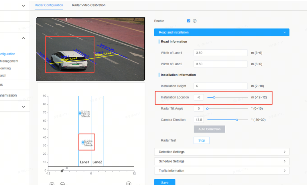
1. Click the Auto Correction button under Camera Direction to perform automatic angle calibration. The system will adjust so that the traffic flow is fully forward‑facing.
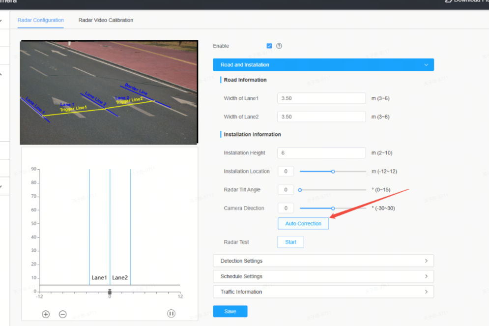
2. Upon successful calibration, a success prompt will appear at the top of the interface. The data will be automatically populated into the camera direction parameter on the Web‑side.
3. Click Radar Test to enter debug mode, and adjust the lane installation position to ensure traffic targets are fully displayed in the radar trace plot.
Notes:
• During auto correction, the underlying system writes radar configurations, which may cause several hundred milliseconds of stuttering in the trace plot. This is normal behavior.
• Auto Correction requires live traffic flow to function. Please ensure normal on‑site traffic volume.
Step5: Auto Calibration(TS5510-GVH model + T_47.8.0.4-R9-C1 version)
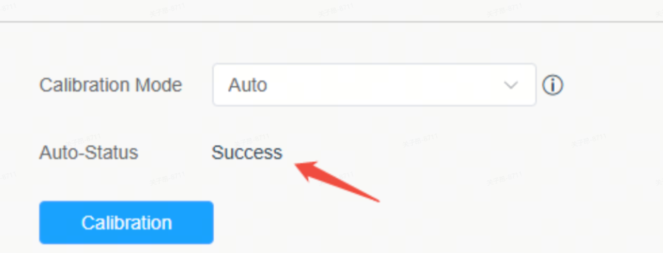
1. Navigate to the Radar Video Calibration page and set the calibration mode to Auto.
2. Click the Calibration button and wait for the progress bar to complete. Calibration succeeds when Auto‑Status shows Success.
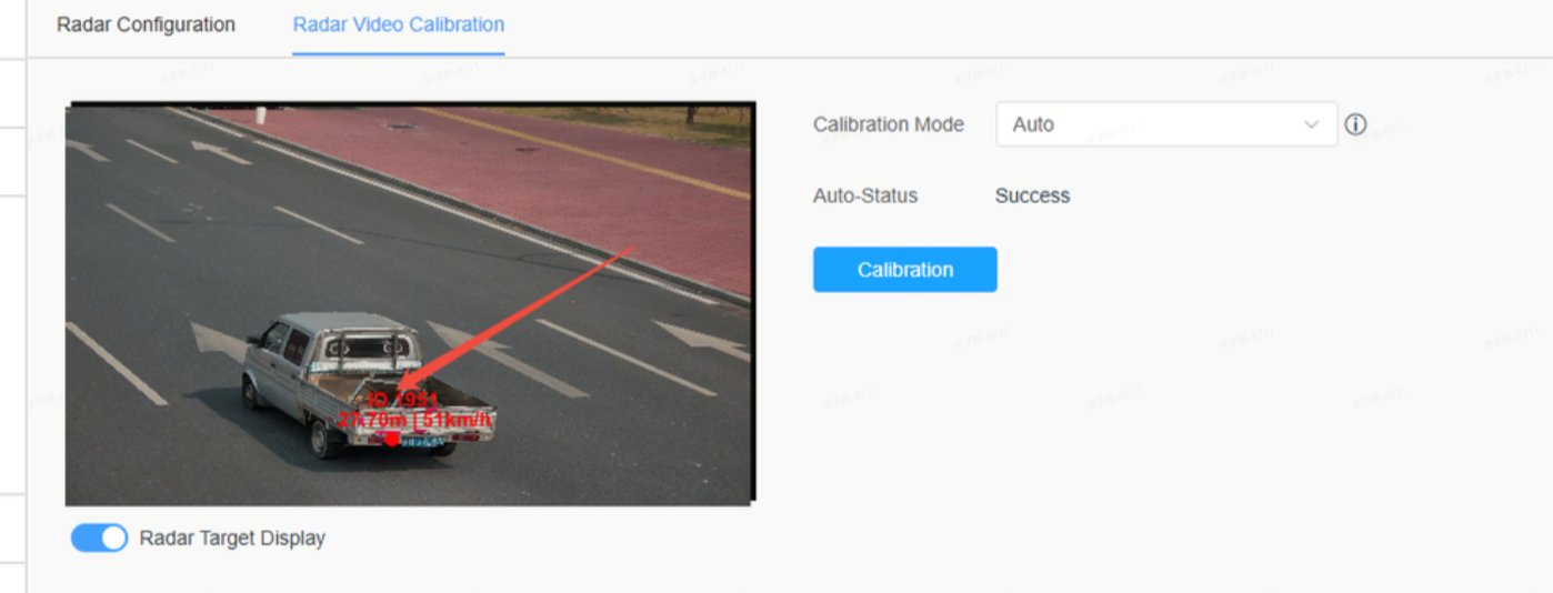
3. Open Radar Target Display, and check whether the radar data points accurately overlay the vehicle. If the alignment is not fully accurate, repeat the calibration until the radar data points are roughly consistent with the vehicle position.
Note:
• Auto Calibration requires live traffic flow to function. Please ensure normal on‑site traffic volume.
Summary & Precautions
• Real-time Validation
Always watch the live trajectory plot while making changes to see immediate feedback.
• Save Settings
You must click Save after finishing all steps, or the calibration will be lost after a reboot.
• Field Test
After configuration, perform a "Drive-by Test" with a vehicle at a known speed to verify accuracy.
• Reset
If the configuration becomes confused, refer to the user manual to perform a Parameter Reset.
3.3 Complete The Remaining Functional Settings
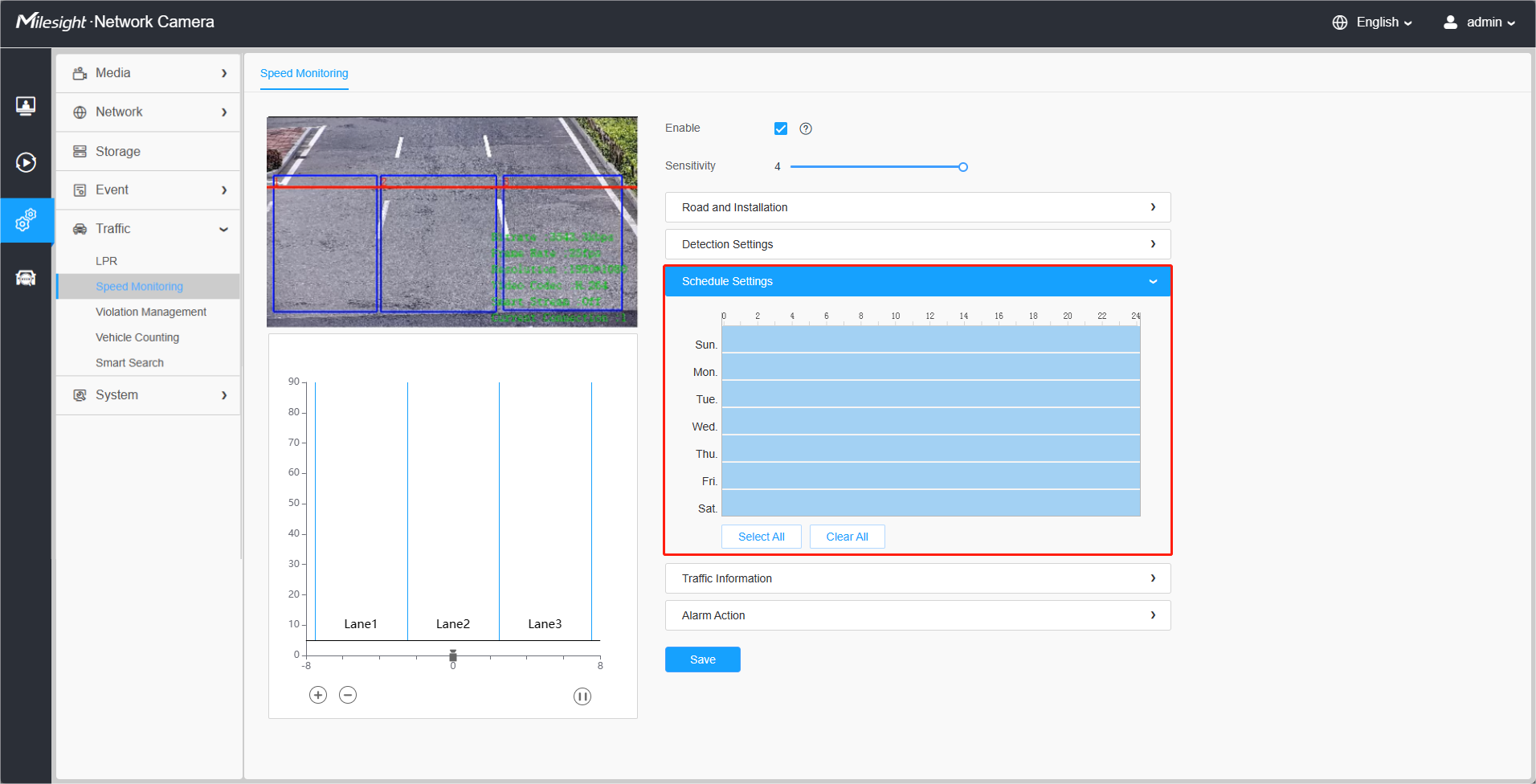
Step1: Schedule Settings.
Set the effective time of traffic detection.
Step2: Traffic OSD Settings.
Customers can choose the information that needs to be displayed in Live Video and the display format, such as color, size, etc.
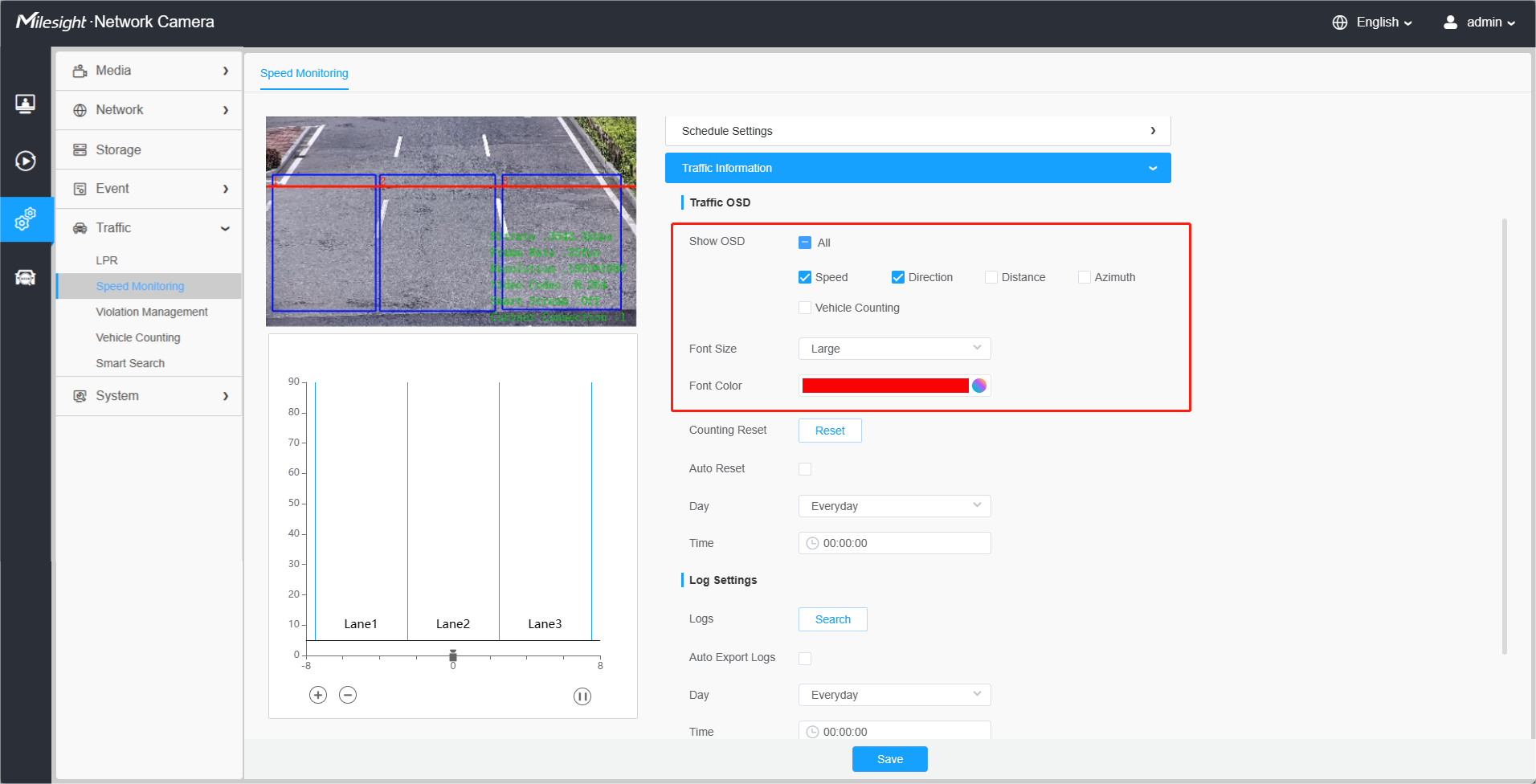
[Show OSD]: Users can choose the information they want to display in Live Video, including Speed, Direction, Distance, Azimuth, and Vehicle Counting.
[Font Size]&[Font Color]: The font size and color of the OSD display, the default size is Medium;
When Speed, Direction, and Vehicle Counting are checked, the Live View interface is displayed as shown in the figure below:
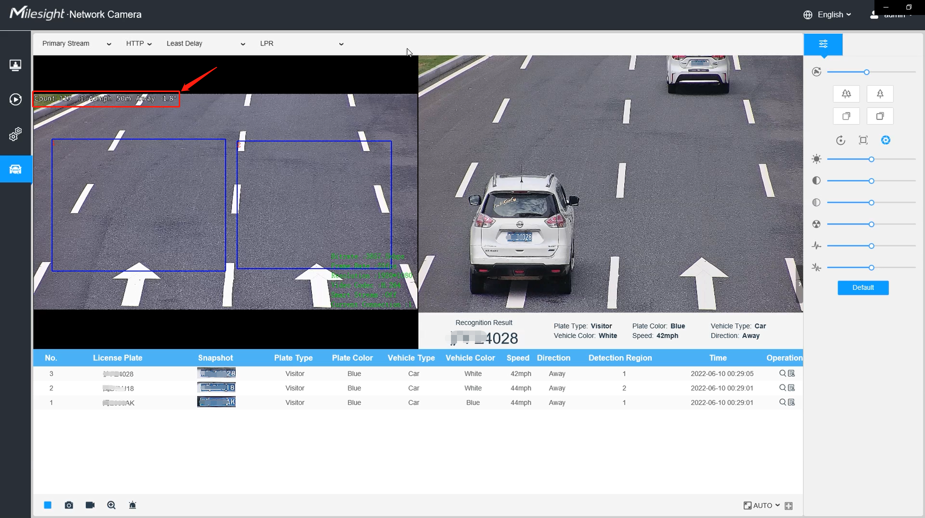
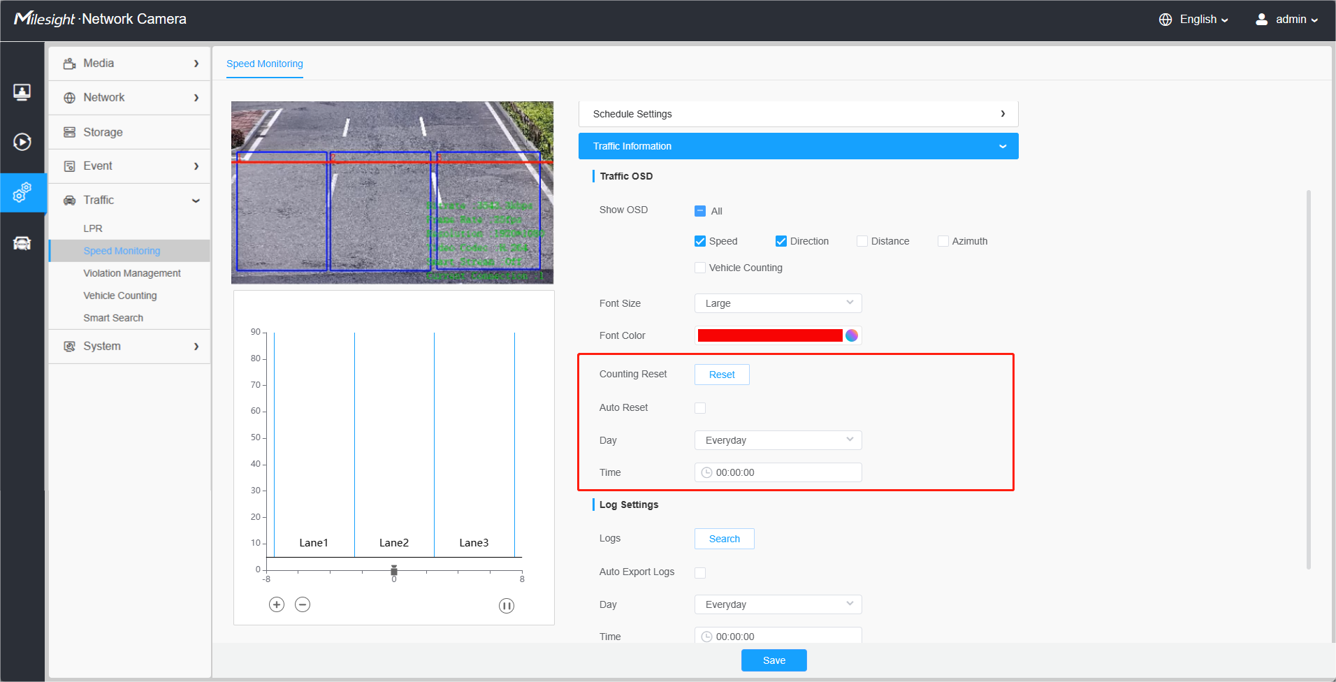
[Counting Reset]: Click the "Reset" button to reset the vehicle count manually.
[Enable Auto Reset]: It automatically clears the vehicle count at regular intervals (Just reset the OSD count for Live Video). After it is enabled, the interface is shown in the figure below. Just follow the prompts to set it.
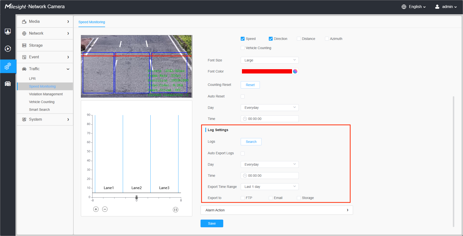
Step3: Log Settings.
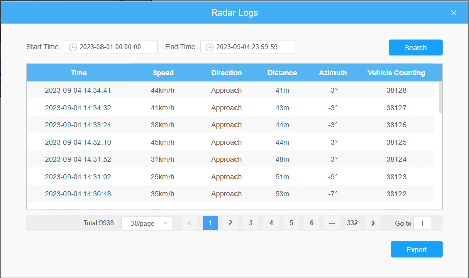
Click the "Edit" button, and a pop-up window, as shown in the figure below, will appear, allowing users to search for various types of logs and supporting the log export function.
Note:The storage and query of radar logs requires the insertion of an SD card
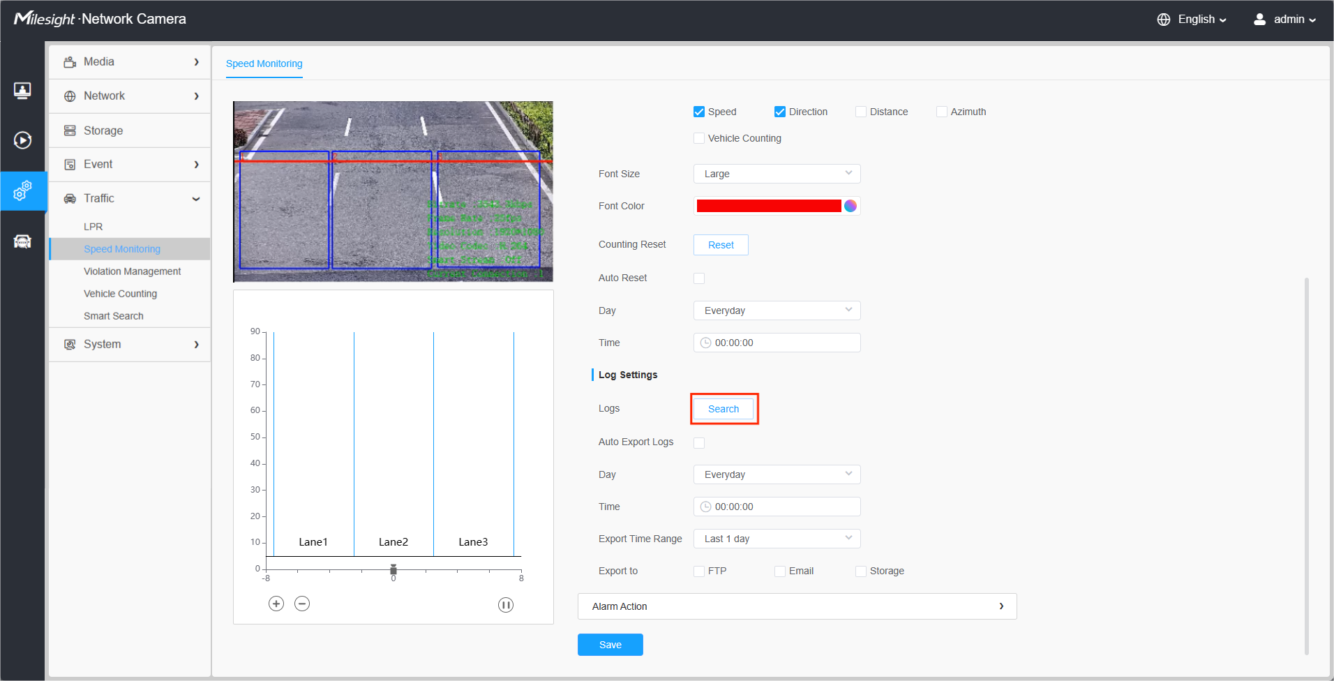
[Enable Auto Export Logs]: Support regular automatic export of logs to FTP, Email and Storage.
Step4: Detection Event.
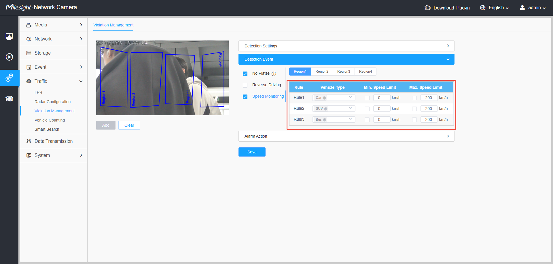
Used to set detection event, such as maximum and minimum speed limit, driving direction limits.
Speed Monitoring
[Region]: Different rules can be set for each detection area.
[Rule]: For a single detection area, you can configure up to 3 rules. For each rule, you can select the vehicle type, maximum speed and minimum speed.(New feature for T_61.8.0.4_AP )
Step5: Alarm Action
This part is the same as the regular alarm settings. For details, please refer to the Milesight Network Camera User Manual. Here is an example of alarm actions for your reference.
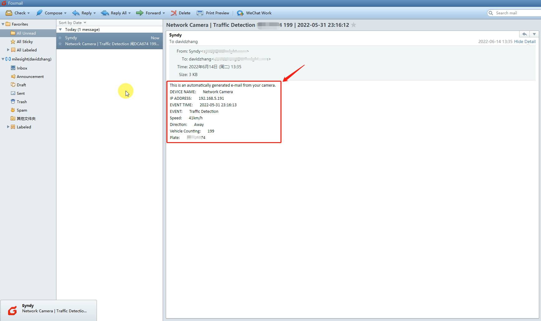
• Send Email
You need to configure the correct email information first. Then, when an alarm is triggered, it will send the detection result to the corresponding email, as shown below, including the license plate number, event type, vehicle speed, etc.
3.4 Live View
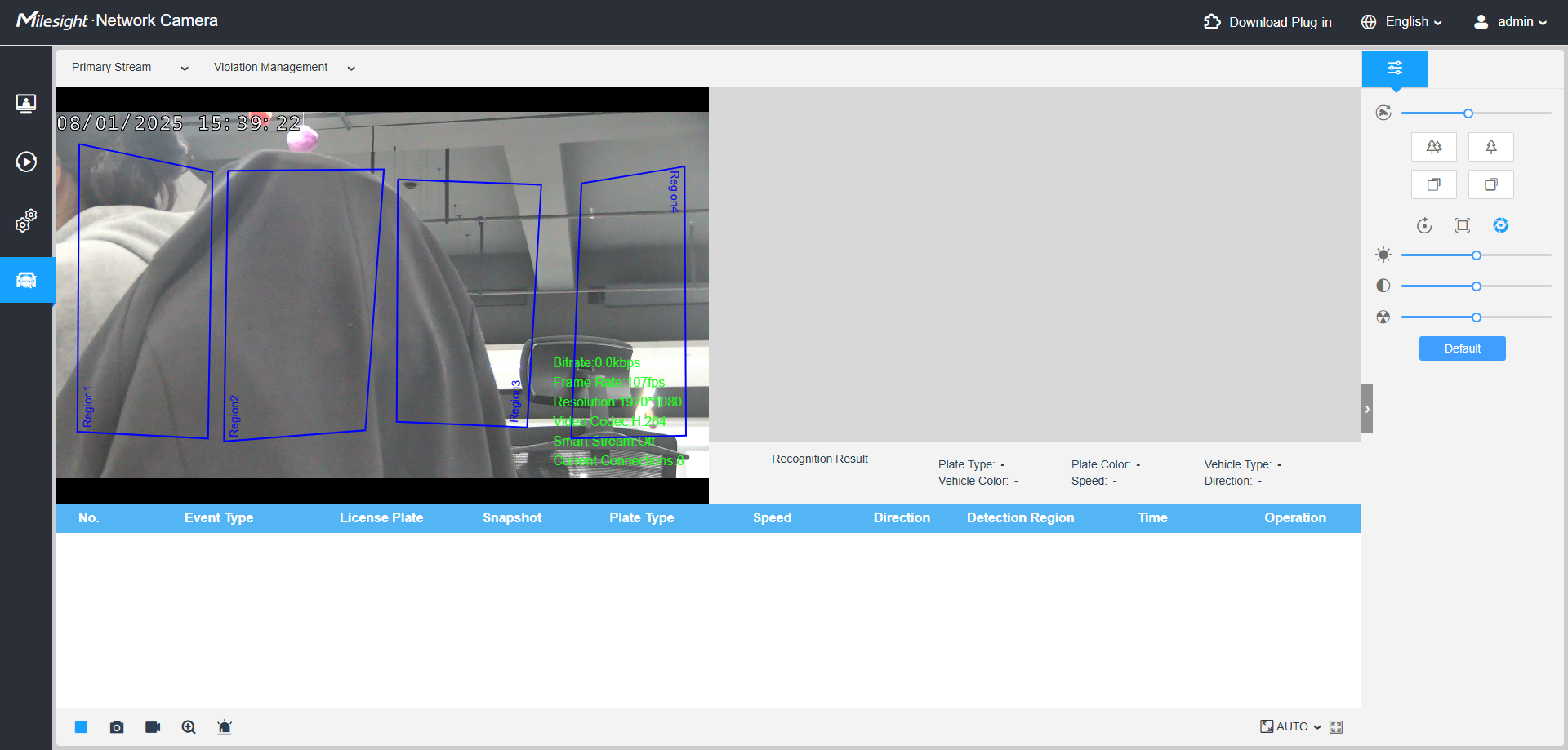
After completing the LPR and Traffic Detection related settings, you can use the related functions of Radar AI LPR Camera normally. The following is the real-time display in the Live View interface:
-END-