
Product Series | Product Model | Version |
E&E Series | MS-C4466-RFILPG1 | T_63.8.0.5 and above |
1. OSDP Protocol Overview
OSDP (Open Supervised Device Protocol) is an open standard protocol for access control and security peripheral communication over an RS-485 bus, published and maintained by the Security Industry Association (SIA).
It is used to reliably transfer control commands, status and event data between the access control unit (master device, ACU) and peripherals such as card readers, cameras and I/O modules (slave devices, PDs), providing access control and security system integrators, device vendors and end system platforms with a unified, interoperable and securely extensible device communication method.
Term | Description |
ACU (Access Control Unit) | The access control controller, the master device on the OSDP bus. It polls slave devices, issues commands and makes access grant/deny decisions. |
PD (Peripheral Device) | A peripheral device, the slave on the bus, such as a card reader, an OSDP-capable camera or an I/O module. It responds to master commands and reports events. |
SC (Secure Channel) | The optional encryption mechanism introduced in OSDP v2. It encrypts bus communication based on AES-128 and is the core security advantage of OSDP over legacy methods. |
SCBK (Secure Channel Base Key) | The Secure Channel base key, 16 bytes long (32 hex characters), used for symmetric key negotiation when establishing the Secure Channel. |
2. What Problems OSDP Solves
2.1 Comparison with Legacy Wiegand Wiring
Dimension | Wiegand | OSDP |
Physical layer | Point-to-point dedicated cabling; each device is wired to the controller individually | RS-485 bus; multiple devices share one cable set (daisy-chaining supported) |
Communication direction | Mostly unidirectional; events can only be "pushed", and the controller can hardly query device status | Bidirectional communication with master-slave polling; queryable, configurable and monitorable |
Device monitoring | Cannot perceive device online/offline status, tampering or other anomalies | Continuous supervised polling; a device dropout is detected promptly |
Security | Plaintext transmission; vulnerable to eavesdropping and forgery | Supports Secure Channel (AES-128 encryption + authentication) |
Interoperability | Many vendor-specific proprietary implementations; high integration and commissioning cost | Open standard; devices from different vendors interoperate |
2.2 Master-Slave Polling Architecture
The core communication method of OSDP is master-slave polling: the master device (ACU) polls each slave device (PD) on the bus by address in turn, and a slave responds only after receiving a command. All interactions are initiated by the master; slave devices never occupy the bus on their own initiative.

2.3 Half-Duplex and Supervised Reporting
• RS-485 is a half-duplex bus; only one party can transmit data at any given moment
• A slave device (such as the camera) sends data only when it receives a command or poll from the ACU, and never floods the bus with unsolicited data
• Event data (such as license plate recognition results) is cached on the slave side and reported with the response at the next poll — it is neither lost nor blocking the bus
2.4 Structured Messages
OSDP uses structured messages over RS-485 for command delivery and event reporting. A message contains fields such as address, command code, data and checksum; with the optional encrypted Secure Channel, messages can be transmitted encrypted and authenticated.
3. Key Protocol Parameters
Parameter | Specification |
Physical layer / signaling | RS-485, half-duplex asynchronous serial |
Serial port settings | 8 data bits, 1 stop bit, no parity (None), no flow control — mandated by the standard, fixed and not configurable |
Baudrate | At least one of 9600 / 19200 / 38400 / 57600 / 115200 / 230400 must be supported; 2400 and 4800 are not supported (the OSDP protocol itself does not cover low-speed rates) |
PD address | 0 ~ 126; each slave device is configured with a unique address on the bus, and the master addresses it by this address |
Protocol version | v2.x (current mainstream; introduces the Secure Channel encryption capability) |
Encryption algorithm | AES-128 |
Key (SCBK) | 16 bytes, usually entered as 32 hex characters, e.g. 00112233445566778899AABBCCDDEEFF |
4. Secure Channel
Secure Channel (SC) is the core security mechanism of OSDP v2. After key negotiation is completed with the SCBK base key, messages on the bus are encrypted with AES-128 to prevent eavesdropping and forgery.
• The OSDP standard does not mandate the use of Secure Channel — SCBK is only required when SC is enabled; however, most vendors on the market enable SC by default for security reasons, and plaintext OSDP communication is considered insecure
• A common security practice in the industry: after SC is established, plaintext communication is rejected to prevent downgrade attacks
• SCBK is retained normally across power loss or reboot; it is cleared on system reset
4.1 Secure Channel Status (Observable on the Device)
Status | Meaning |
Disconnected | The camera fails to connect to the OSDP master (physical link or parameter mismatch) |
Secure Channel Inactive | The link is up but not encrypted — the Secure Channel is not active (plaintext communication, insecure) |
Secure Channel Active | The Secure Channel is active and communication is protected by AES-128 encryption (normal operating state) |
5. Common OSDP Commands and Messages
5.1 Command Quick Reference
Command / Message | Direction | Purpose |
OSDP_POLL | ACU → PD | Polling command; the master periodically asks the slave whether it has data/events to report. It is the heartbeat that keeps the bus running. |
OSDP_RAW | PD → ACU | Reports raw card data (raw bit array). In ANPR scenarios it is used to report license plate data: the message contains a format code, a bit count and the license plate ASCII data; up to 64 bytes per message |
OSDP_OUT | ACU → PD | Remotely controls the PD's digital outputs (relays), e.g. Output #0 corresponds to Relay 1; the PD returns an ACK to confirm after execution |
OSDP_ISTAT | ACU → PD | Requests the PD's current digital input status (Input #0/#1 correspond to the physical input terminals) |
OSDP_ISTATR | PD → ACU | Report on digital input status changes (carried back in the polling response) |
OSDP_ACK | PD → ACU | Acknowledgement response, indicating that the master's command has been correctly received and executed |
OSDP_MFG | Bidirectional | Vendor-defined command extension (some vendors' access control boards broadcast MFG commands, which slave devices need to handle for compatibility) |
5.2 Master-Slave Polling Interaction Sequence
Taking "empty poll → license plate event report" as an example, the message exchange between the ACU and the camera (PD) on the bus is as follows:
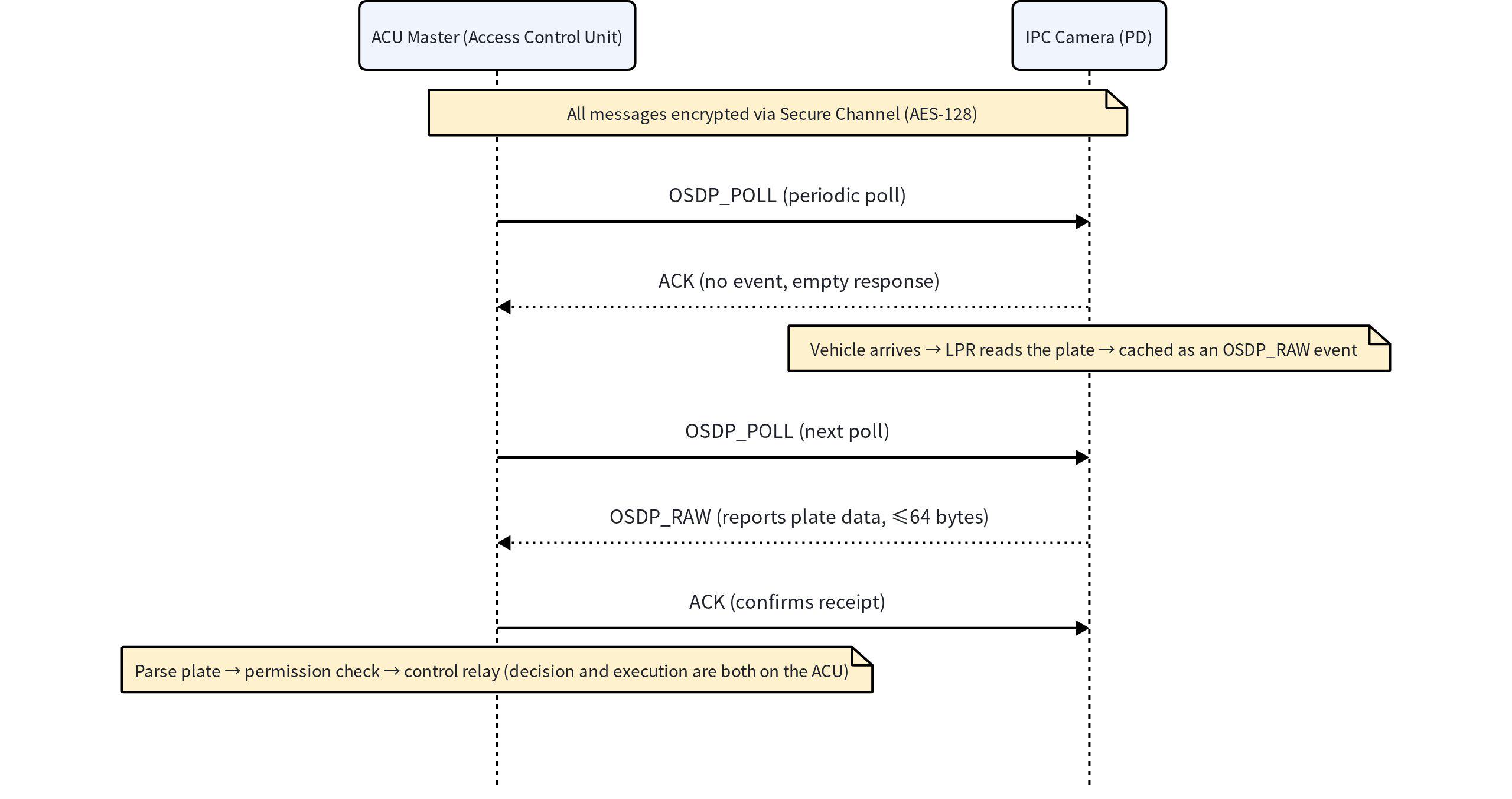
On the half-duplex bus, the camera responds only when polled; events are cached first and then carried out with a response, so they are neither lost nor blocking the bus.
5.3 Typical Data Flow of an ANPR Camera

If camera-side linked output is needed, the ACU can drive the PD's relays via OSDP_OUT (Nedap ANPR-LUMO adopts exactly this mode); changes of the camera's digital input status are reported via OSDP_ISTATR in the polling response, and the ACU can also proactively query them at any time with OSDP_ISTAT.
6. Application Design: Camera Integration with Access Control
6.1 Role Positioning: Minimal Business Loop
• The camera acts as the slave device (PD) of the access control system, responding to commands and transmitting events
• It does not transfer complex business data over OSDP; instead, it completes the minimal business loop of sensing and control
• The camera does not participate in the final access decision and does not directly control the door lock or the barrier; all permission, schedule and policy logic is handled by the access control system
The responsibility split across the whole business chain is shown in the figure below — the camera only performs "sensing and reporting", while the access control system completes "decision and execution":

6.2 Web Configuration Items (System → Interfaces → RS485)
Item | Description |
Protocol | Drop-down single choice: Pelco-D / Pelco-P / OSDP. After OSDP is selected: PTZ Address is hidden, and OSDP Address and OSDP SCBK items appear; 8 data bits, 1 stop bit, parity None and flow control None are fixed and grayed out (required by the standard); default baudrate 9600 |
Baudrate | In OSDP mode: 9600 / 19200 / 38400 / 57600 / 115200 / 230400 selectable (2400 and 4800 hidden); Pelco-D/P mode keeps the original options unchanged. Default 9600 |
OSDP Address | Input box, an integer from 0 to 126, default 0. The master addresses this device by it; out-of-range input triggers a red hint "Valid range: 0~126" |
OSDP SCBK | Masked input box (toggle display with the eye icon); only 0-9 A-F a-f allowed; must be 32 hex characters (16 bytes). The device enables Secure Channel by default at the bottom layer, so this field is required; retained across power loss/reboot, cleared on system reset |
Secure Channel Status | Read-only status display: Disconnected / Secure Channel Inactive / Secure Channel Active |
6.3 Data Transmission Requirements
• Must support the OSDP v2.x protocol stack
• After configuration, the IPC performs license plate recognition and, when an event is triggered, caches the LPR result and the event; it reports them upon receiving the master's OSDP command. The data format follows the OSDP standard protocol, and the plates of all supported countries are expected to be transmitted correctly
• Closed-loop validation through interoperability testing with the access control controller — the Secure Channel is established normally, the device responds to master commands, and events are sent and parsable by the master
6.4 Integration Summary
Enable OSDP on the camera, configure a unique PD address, and match the ACU's communication parameters (baudrate, SCBK, etc.) — then OSDP communication between the camera and the access control controller is established over the RS-485 bus:

Corresponding to the Secure Channel Status field in the web UI: when the configuration and wiring are correct and the address, baudrate and SCBK all match the ACU's, the status changes from Disconnected to Secure Channel Active.
7. Lab Validation Procedure
The following are the complete steps of the OSDP interoperability test of the IPC using the Integriti Pro access control management software and the 996035 PCB&K access control board.
1. Set up the environment: Install the Integriti Pro software (server + System Designer) and complete activation; connect the access control board (P12 port) to the PC with a USB 2.0 Type-B cable, and confirm the board is online in the Navigation Tree
2. Configure the OSDP SCBK (access control side): Right-click the controller → Edit → expand OSDP Options → set OSDP Crypt Mode to User Programmed Key, enter the SCBK identical to the IPC's, and click Save
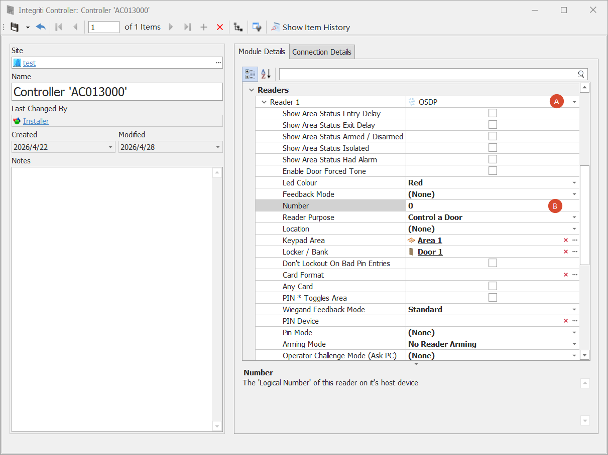
3. Configure the Reader: Set Reader 1 to the OSDP type, fill in Number with the device address (0~15), set Reader Purpose to Control a Door, and click Save
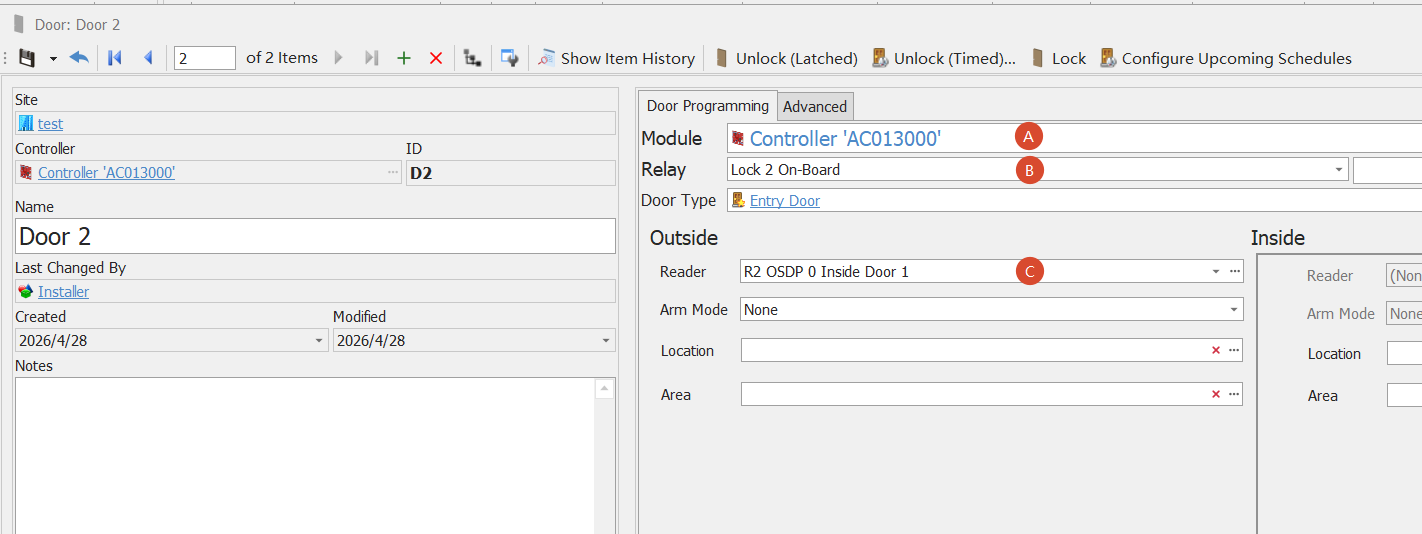
4. Configure the Door: Access Control → Doors → Add New: select the current control board for Module, select an on-board relay for Relay (e.g. Lock On-Board), select the corresponding OSDP Reader, and click Save
5. Configure the Card Template: Card Templates → Add New, select SIFER Direct 88 for Card Format, and click Save
6. Configure the Card (license plate number): Cards → Add New: select the template from the previous step for Card Type, enter the encoded plate number for Card Number, and confirm Status is Active
7. Configure the User: Home → Users → Add New: enter the username, associate the card and the door, and click Save
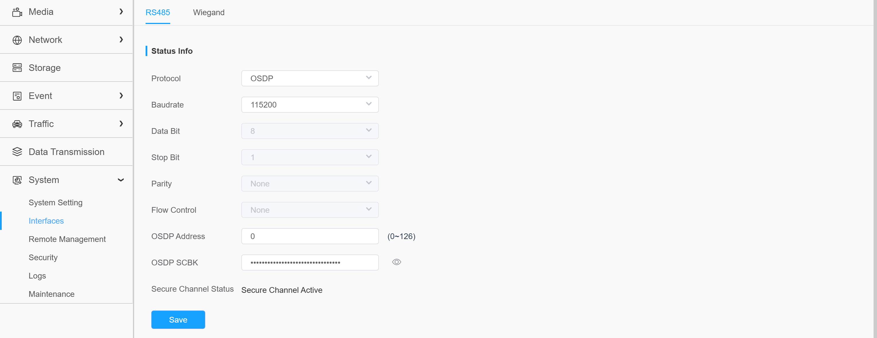
8. Configure the IPC: On the IPC web UI, System → Interfaces → RS485: set Protocol to OSDP, match the baudrate with the access control board (the board only supports 115200), set the OSDP address and SCBK identical to the access control side, and click Save
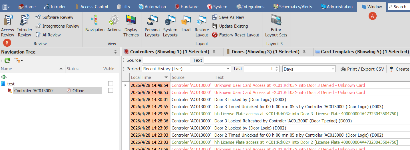
9. Functional test: Enable LPR; a vehicle passes → the camera recognizes the plate → the access control board parses it and controls the relay switching; the corresponding access logs can be viewed in Access Review, closing the validation loop
7.1 UI Screenshots of Key Steps
Step 2 · Configure the OSDP SCBK on the access control side (Integriti Pro): Set OSDP Crypt Mode to User Programmed Key and enter the key identical to the IPC's

Step 3 · Configure the Reader (Integriti Pro): Set Reader 1 type to OSDP (A), fill in Number with device address 0 (B)
Step 4 · Configure the Door (Integriti Pro): Select the control board for Module (A), the on-board relay for Relay (B), and the corresponding OSDP Reader (C)
Step 8 · Configure OSDP on the IPC (System → Interfaces → RS485): Set Protocol to OSDP, match the baudrate with the access control board (115200), enter an address within 0~126 for OSDP Address, enter the OSDP SCBK as masked input (toggle display with the eye icon); the Secure Channel Status is displayed in real time below
Step 9 · Functional test logs (Access Review): The green License Plate access entries are the access events triggered after the camera reported the plate over OSDP (License Plate 400000004A47323043504750 is the encoding of plate JG2OCPGP)
7.2 License Plate Number Encoding Format (SIFER Direct 88 / OSDP_RAW Passthrough)
Hexadecimal, 24 characters in total. The first byte is the plate length × 8 (i.e. the bit count), zero-padded where applicable:
Plate Number | Encoding (Hex) |
JG2OCPGP (8 characters) | 400000004A47323043504750 |
JG20GP (6 characters) | 3000000000004A4732304750 |
The first byte 0x40 = 8×8 (8 characters × 8 bits), and 0x30 = 6×8; the tail is the plate number's ASCII in hexadecimal (4A47… stands for "JG…").