
CMS Version | V2.4.0.18-r1 or above | Update | 2025.2.20 |
1.Introduction
This document primarily introduces the capability boundaries implemented in CMS. The introduction will cover the CMS's Device, Live View, and Playback modules separately.
2.Background
Since the CMS is a free video management software designed for small to medium-sized projects, in order to align with the product's positioning and ensure stability, limitations have been imposed on the number of device connections and the number of channels that can be simultaneously previewed, played back, or recorded.
3.CMS Channel Addition Limitations
The following limitations on the number of addable channels have been implemented:
1. The maximum number of devices that can be added is 256.
2. The maximum number of P2P devices that can be added is 32.
3. The maximum number of NVRs that can be added is 32.
4. Live View can simultaneously play up to 128 channels.
5. Playback can simultaneously play up to 16 channels.
Regarding the changes to the device, live view, and playback interfaces of CMS, we will provide corresponding explanations below.
3.1Device
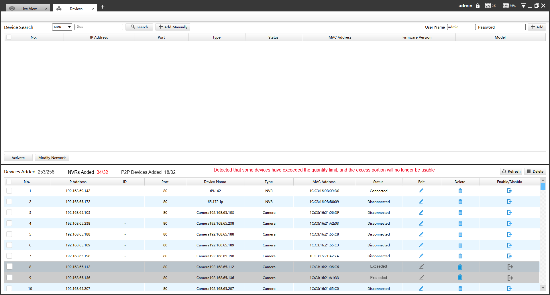
In CMS, two text labels are added above the device list, following "Devices Added": "NVRs Added M/32" and "P2P-Devices Added N/32", where M and N represent the number of added NVRs and P2P devices, respectively, with a maximum value of 32.
Note:
Since CMS is a free video management software designed specifically for small and medium-sized projects, we have updated its device limitation mechanism to align with the product’s positioning. If the devices added in the old version exceed the current limit, you may encounter the following situation after upgrading to the new version.
• If only the number of NVRs exceeds the limit of 32 devices, retain the first 32 NVRs in the list and gray out the remaining ones.
• If only the number of P2P-connected devices exceeds the limit, retain the first 32 P2P devices in the list and gray out the remaining ones.
• If both NVR and P2P-connected devices exceed the limit, prioritize P2P devices over NVRs. Retain the first 32 P2P devices in the list. If there are P2P-NVRs, count them towards the NVR limit. Retain the first 32 NVRs in the list, and gray out any excess devices.
3.2Liveview
Currently, the CMS software allows a maximum of 128 video channels to play simultaneously. However, the number of channels that can play simultaneously varies depending on the decoding performance of different computer graphics cards. For detailed on the decoding performance of the CMS, please refer to the below document.
Since the CMS allows for multi-screen setups and the number of channels occupied by the alarm screen is dynamically changing, the limitation strategy is as follows:
Regardless of the number of auxiliary screens connected, only one screen is allowed to serve as the Alarm Screen. The default number of channels occupied by the Alarm Screen is determined by the selected view. Specifically, when selecting the 1/4/9/16/36/64 view, the default number of occupied channels corresponds to the number of views selected.
• If an auxiliary screen is configured as the Alarm Screen first:
Using the Alarm Screen with an N-view selection as an example, where N can be 1/4/9/16/36/64: If an auxiliary screen is first selected as the Alarm Screen, it will occupy N channels. The main screen plus the remaining auxiliary screens will have 128-N channels available.
• If the other auxiliary screens are configured first and then the Alarm Screen is configured:
1. If there are available channel resources:
When switching to the Alarm Screen, the default view is allocated based on the remaining channel resources, and other views are determined by the available channel resources. For example, if the remaining available channels are 10, then when Auxiliary Screen 1 switches to the Alarm Screen, the default view will be 9. Other view icons will display normally. When attempting to switch views, a logical check is performed: switching is allowed only if the remaining channels are greater than or equal to the view number. Otherwise, a message will be displayed: "The number of occupied channels has reached 128, operation failed."
2. If there are available channel resources:
If there are no available channel resources and the Alarm Screen is selected in the multi-screen setup, clicking OK will prompt the message: "The number of occupied channels has reached 128, operation failed."
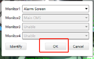
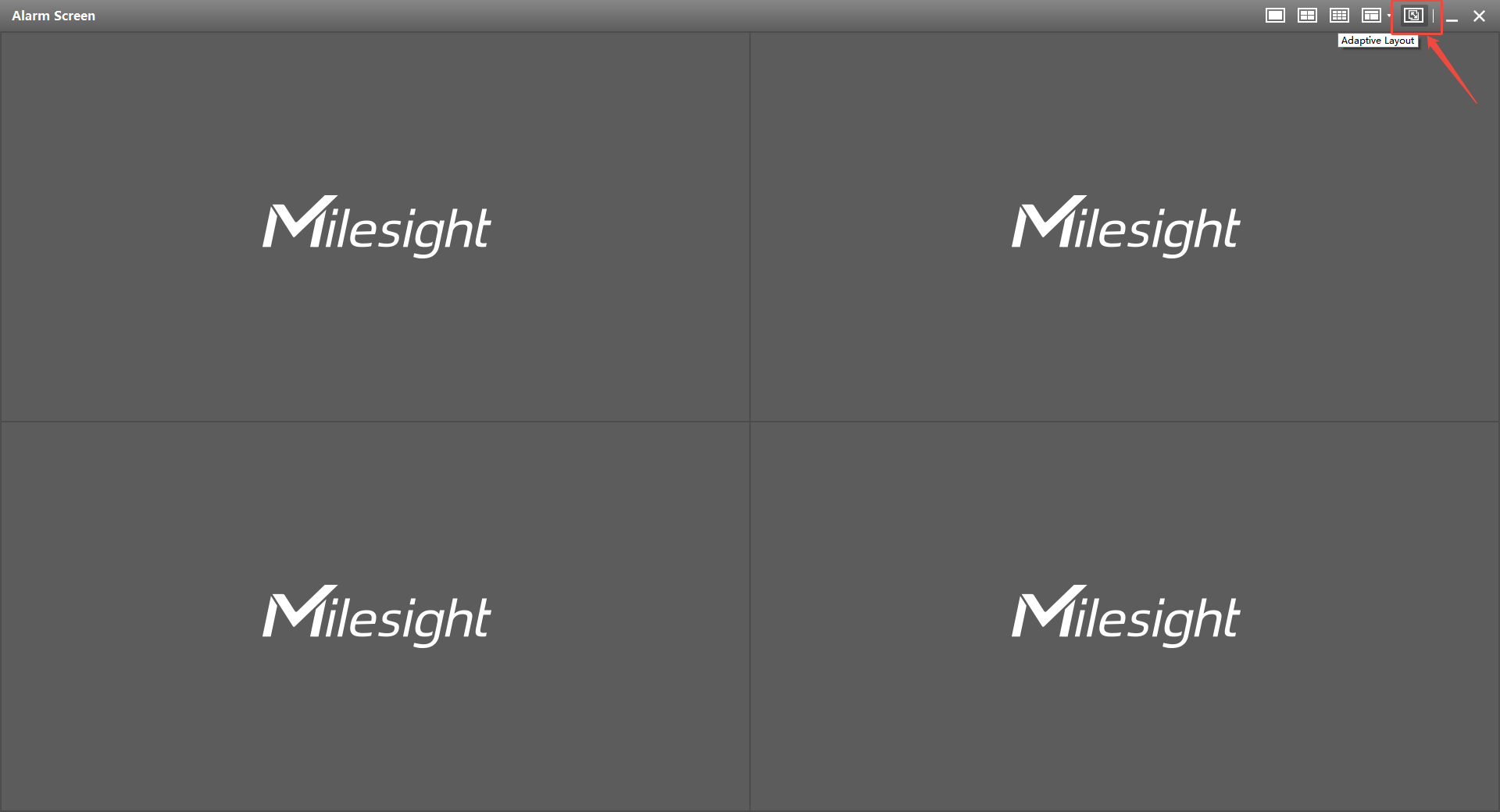
Due to conflicts between the adaptive view and multi-screen channel resource allocation, the adaptive view strategy for the Alarm Screen has been adjusted as follows:
• If there is one auxiliary screen connected and it is set as the Alarm Screen, the adaptive view is supported. However, if you attempt to switch to another external screen, a prompt will appear: "To switch to another screen, you must first disable the 'Adaptive Layout' on the Alarm Screen."
• If there are 2 or 3 auxiliary screens connected, the adaptive view is not supported when any screen is set as the Alarm Screen. The “Adaptive Layout” icon will be grayed out and unresponsive when clicked.
3.3Playback
The CMS software allows a maximum of 16 playback channels to play simultaneously on the main screen, so the layout supports up to 16 views. However, the number of playback channels that can play simultaneously varies depending on the decoding performance of different computer graphics cards. For detailed on the decoding performance of the CMS, please refer to the below document.
Layout settings:
• Supports switching between 1, 4, 9, 1+7, 4+4, and 16 view layouts.
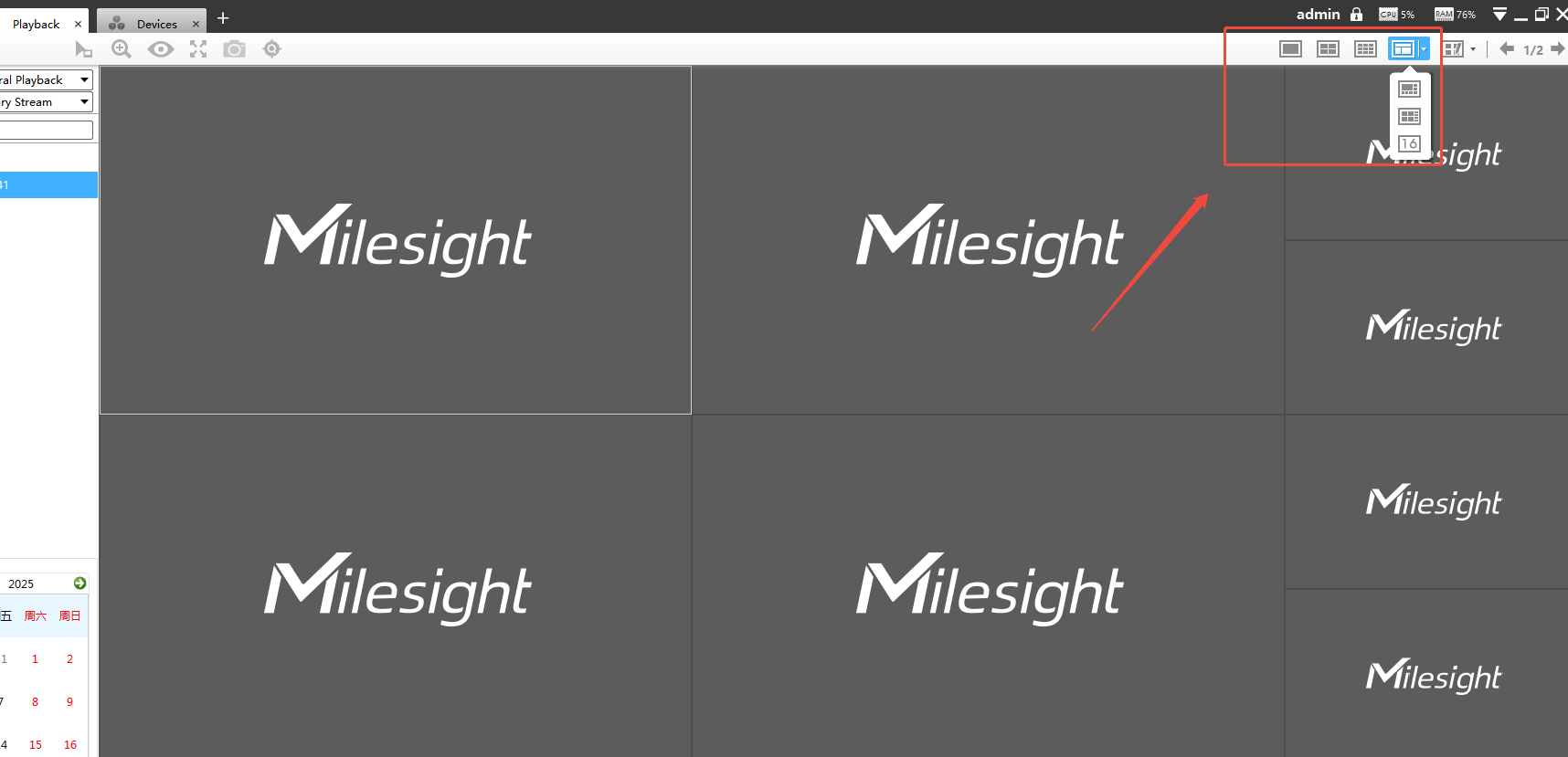
• Right-side page flipping logic: 1 view corresponds to 1/16 page flipping, 4 views correspond to 1/4 page flipping, 9/1+7/4+4 views correspond to 1/2 page flipping, and 16 views correspond to 1/1 page flipping. Note that when flipping pages in the 9-view layout, since only 16 channels are supported, the 2nd page will have only 7 channels.
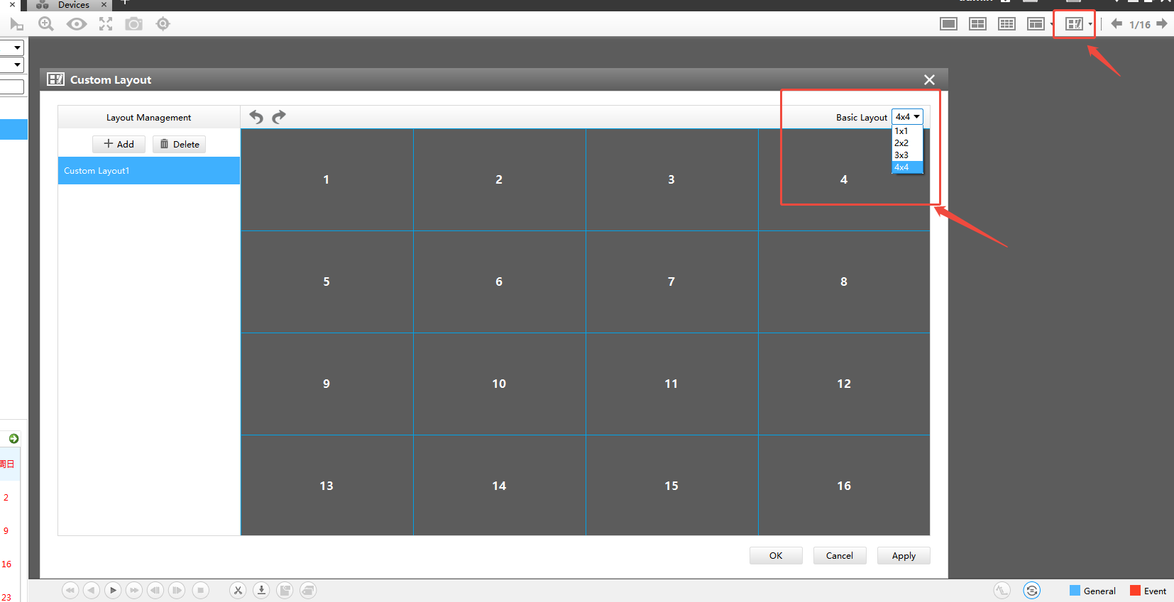
• Custom Layout: The custom layout Basic option supports 1×1, 2×2, 3×3, and 4×4 layouts. When clicking Add, the default view is 4×4.
———— END ————