
Version | 1.0 | Update | 2026.9.9 |
Document Purpose
This guide standardizes the pre-installation site survey process for Milesight Traffic C Series traffic camera. It defines the survey workflow, key inspection criteria, and technical benchmarks across road conditions, mounting structures, lighting environments, and traffic patterns — ensuring that every deployment is optimally planned for stable ANPR performance, reliable vehicle detection, and long-term operational integrity.
1 Road & Lane Conditions
1.1 Survey Requirements Summary
Record the following data points during the site visit. Any condition outside the recommended values constitutes a non-standard scenario and requires pre-sales engineering review before deployment.
Survey Item | Required Data Point | Recommended / Ideal Value |
Road Type | Urban road | Urban arterial |
Number of Lanes | Total lanes at the intersection or segment | 1–3 lanes (overhead); 1–2 lanes (side-mount) |
Single Lane Width | Field-measured width (m) | 3.0 m – 3.75 m per lane |
Lane Stability | Fixed lanes or temporary/variable lanes? | Fixed lanes; no ad-hoc lane changes |
Lane Curvature | Straight, slight curve, or significant curve? | Fully straight within camera field of view |
Obstructions | Trees, poles, canopies, barriers, signage | No obstructions between lens and road surface; For radar models: no guardrails, signs, or walls in beam path |
Dedicated Lane Types | Bus lane, emergency lane, or mixed use? | Dedicated lanes supported; avoid dual-deck bus routes |
1.2 Supplementary Notes
Figure 1-1 | Representative installation environments
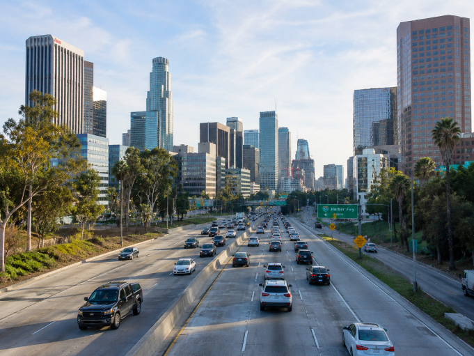
Fig. 1-1 Urban Arterial Road — ideal scene
ℹ | Lane Stability Variable lanes are supported, but fixed lanes are strongly preferred. When a vehicle crosses multiple detection zones during a lane change, the system may generate duplicate captures and license plate pushes, which can compromise enforcement data accuracy. |
Figure 1-2 & 1-3 | Lane curvature — acceptable vs. unacceptable
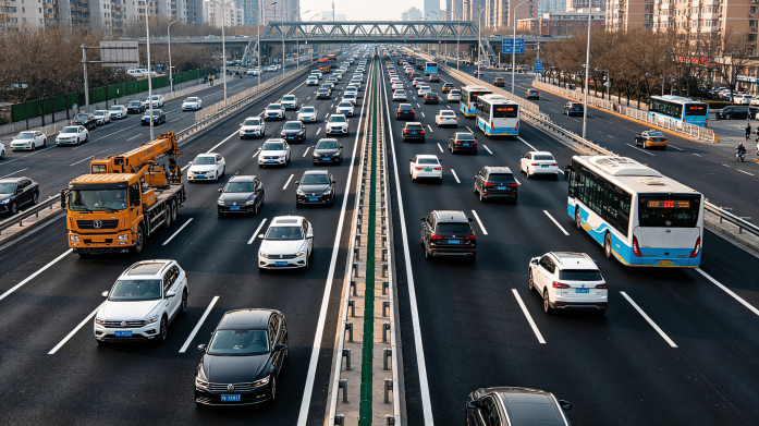
Fig. 1-2 Acceptable — slight curve, road straight within FOV

Fig. 1-3 Unacceptable — pronounced curve within FOV
ℹ | Lane Curvature Fully straight lanes are required. A slight curve (Fig. 1-2) may be acceptable if the road appears completely straight within the camera's field of view. Pronounced curvature (Fig. 1-3) prevents reliable plate capture and does not meet installation requirements. |
ℹ | Obstructions — Radar Models No obstructions should exist between the lens and the road surface. For radar-equipped models, guardrails, road signs, walls alongside side roads, parked vehicles, and building facades can reflect radar waves, causing multipath effects. This produces phantom targets and speed measurement errors. Survey must confirm a clear radar beam path.(See Fig 1-4) |
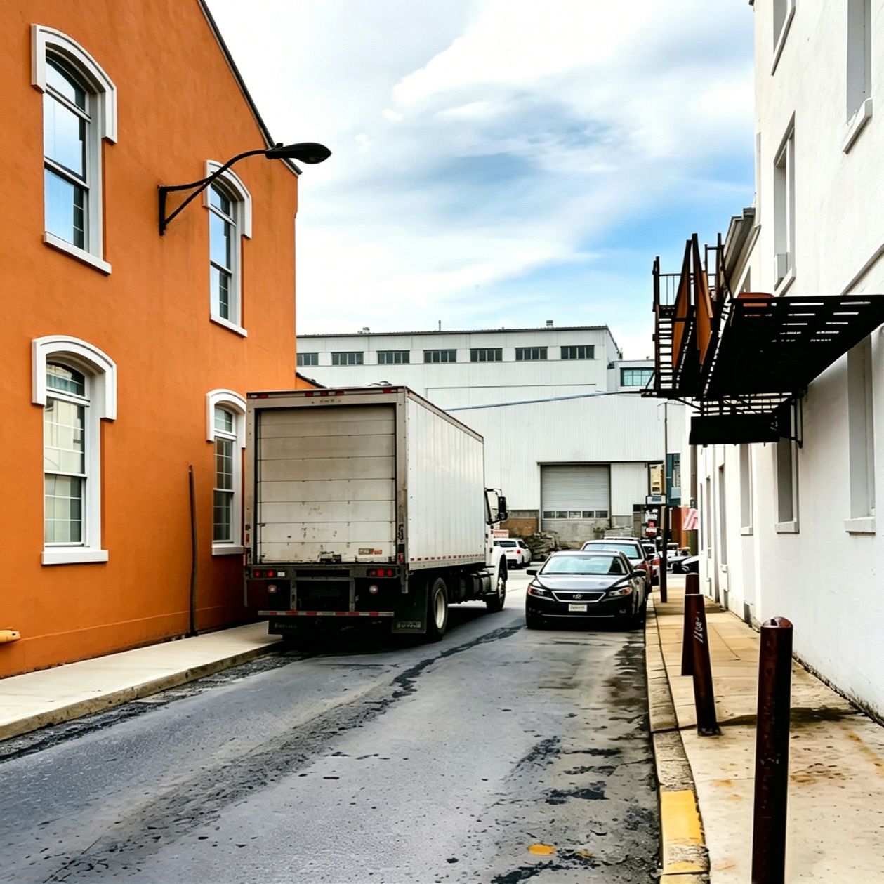
Fig. 1-4 Radar multipath effect — guardrails and wall reflections causing ghost targets
ℹ | Bus Lanes & Emergency Lanes Bus license plate recognition is supported. However, do not install the camera on the bus-lane side of the gantry or pole. A passing bus may temporarily block the camera's field of view, causing missed detections on adjacent lanes. Dual-deck buses should also be excluded from detection zones. |
⚠ | Non-Standard Scenario If any field measurement falls outside the recommended values, classify the site as a non-standard scenario and contact the Milesight pre-sales engineering team for assessment and validation before proceeding. |
2 Mounting Structure & Installation Parameters
2.1 Mounting Structure Requirements
Select and evaluate the mounting structure before finalizing the installation point.
1.Overhead Gantry
Provides the most stable platform and ideal overhead angle for multi-lane coverage. Preferred for all new deployments.
2.Side Pole
3.Outrigger / Cantilever Arm
Acceptable where the above options cannot be installed; requires engineering sign-off on structural loads.
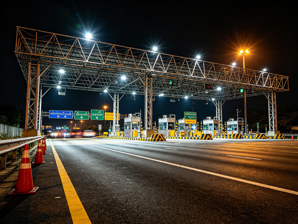
Fig. 2-1 Overhead gantry installation — recommended configuration
Structural & Electrical Checklist
Before finalizing any mounting structure, verify the following:
Structural
• Rated load capacity exceeds total equipment weight (camera + enclosure + cabling)
• Cantilever length and extension angle are compatible with camera installation requirements
• Crossbeam, pole, or arm height falls within the permitted installation height range
• Wind load rating matches local environmental conditions and device frontal area
• Structural rigidity prevents high-frequency micro-vibration that would cause plate blur
Mounting Interface
• Cross-section dimensions of the beam or pole are compatible with the camera bracket
• Sufficient space available for the equipment enclosure
Power & Cabling
• Camera power supply: 12 V DC/ PoE(802.3at)
• Total power budget meets all device requirements
• Sufficient conduit bore and cable tray space for routing
Environmental Protection
• All cable entries and enclosure penetrations are fully weatherproofed
• Drainage paths prevent liquid ingress into the device
Network
• Stable network connection available; fiber optic recommended
Surge & Lightning Protection
• Reliable earth grounding in place (surge protection module recommended)
• Surge protective device (SPD) installed to safely dissipate lightning and switching transients
⚠ | Non-Standard Scenario If the proposed mounting structure does not fully meet the checklist above, contact the Milesight pre-sales engineering team before proceeding. |
2.2 Core Geometric Parameters
The parameters below define the physical geometry of the camera installation. Deviating from the recommended values without engineering review may result in reduced capture rate, plate blur, or missed detections.
Model/Parameter | Installation Height | Pitch | Yaw | Radar Vertical Pitch Angle | License plate height within FOV | Maximum detection range for side-mounted lateral detection | Maximum longitudinal detection range |
TS4466-X4RGPE | 3-6m | 15°–25° | 0°-15° | / | 32 pix (Full Snapshot) | 5m | 30m |
TS4466-X4RIPG1 | / | 40m | |||||
TS5366-X12RIPG1 | / | 60m | |||||
TS8266-X4RIPG1 | / | 50m | |||||
TS4466-X4RIVPG1 | 3° | 30m | |||||
TS4466-RFIVPG1 | 3° | 15m | |||||
TS8266-X4RIVPG1 | 3° | 30m | |||||
TS8266-RFIVPG1 | 3° | 15m | |||||
TS4466-X4RIWG1 | / | 50m | |||||
TS8266-X4RIWG1 | / | 60m | |||||
TS2967-X12TPE | / | 40m | |||||
TS2967-X23TPE | / | 70m | |||||
TS4467-X20RPE | / | 80m | |||||
TS5367-X12PE | / | 40m |
ℹ | Installation Geometry Reference Refer to the Milesight Intelligent Traffic Cameras Installation Guide (TrafficC Series) for annotated parameter diagrams and the installation tutorial video. PE model: https://resource.milesight.com/milesight/security/document/user-manual/intelligent-traffic/milesight-intelligent-traffic-cameras-installation-guide-road%20traffic-management.pdf PG1 model: https://drive.google.com/file/d/1BNtif9_rENk-5PctLMYOFSY96QAIvrIH/view?usp=sharing Radar model: youtube.com/watch?v=u88gNAdrJnM&list=PLBahHHIE0sIP8HWyRh4CoEWTpVLGCSsUT&index=9 |
License Plate Pixel Height Verification
After provisional camera positioning, verify the plate pixel height using the following procedure:
1. Download and export a full-resolution vehicle capture image from the camera.
2. Open the image in Windows Paint (or equivalent raster editor).
3. Use the rectangle selection tool to draw a bounding box tightly around the license plate in the image.
4. Read the pixel dimensions of the selection box displayed in the status bar (bottom-left of the Paint window).
5. Confirm that the plate height value meets or exceeds 20 px; 32 px or above is the recommended target.
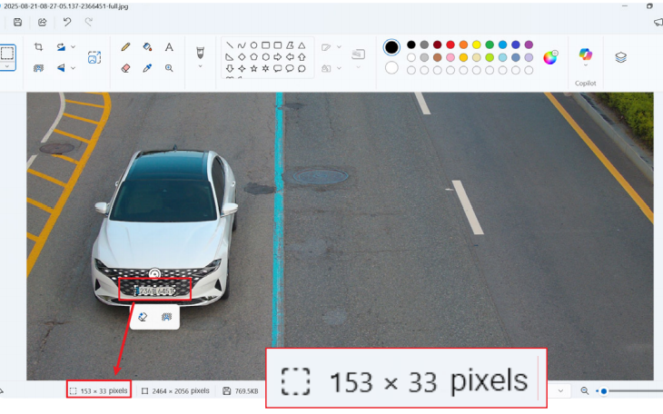
Fig. 2-2 Windows Paint selection showing plate pixel height in status bar
⚠ | Non-Standard Scenario If the proposed mounting structure does not fully meet the checklist above, contact the Milesight pre-sales engineering team before proceeding. |
3 Lighting & Environmental Conditions
3.1 Survey Requirements Summary
Survey Item | Required Data Point | Recommended / Ideal Value |
Daytime Backlight | Does the camera face the sunrise or sunset direction? | No strong backlight; avoid direct solar glare onto the lens |
Nighttime Direct Light | Sodium lamps, LED spotlights, or any strong source aimed at camera? | Uniform illumination; no direct strong-source glare; avoid low-color-temperature sources (e.g., sodium lamps) or uncontrolled strobes |
Reflective Surfaces | Billboards, glass curtain walls, reflective road signs? | No reflective surfaces in the camera's field of view |
Weather & Atmosphere | Local rain, fog, sandstorm, or snow frequency? | No extreme weather events (blizzards, sandstorms, etc.) |
Ambient Illuminance | Measured lux level at the site (use a lux meter) | ≥ 80 lux for vehicle attribute recognition |
3.2 Supplementary Notes
ℹ | Daytime Backlight A camera facing the rising or setting sun will experience severe backlight conditions. Overall backlight causes license plates to appear too dark in the early morning; direct solar glare onto plates causes overexposure. |
ℹ | Nighttime Direct Light Sources Strong light directed at the camera at night can force the device to switch back into daytime mode, or cause severe overexposure in night mode, degrading image quality. Illuminated advertising signs (see Fig. 3-1) and oncoming high-beam headlights can also introduce lens flare or ghosting artifacts. Low-color-temperature sources such as sodium vapor lamps are particularly problematic. |
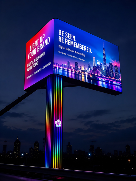
Fig. 3-1 Illuminated billboard causing lens flare / ghosting at night
ℹ | Reflective Surfaces The camera's field of view must be free of surfaces that reflect strong light back toward the lens. Foliage, advertising panels, glass facades, and wet pavement can all act as secondary light sources under certain conditions. |
ℹ | Supplemental Illumination If measured ambient illuminance falls below 80 lux, or if vehicle attribute recognition is required at night, an auxiliary white-light or IR illuminator must be specified as part of the installation design. |
4 Traffic Behavior & Target Characteristics
The following traffic patterns and vehicle mix characteristics can negatively impact system performance. Document each condition during the site survey and assess the deployment suitability accordingly.
Frequent Lane Changes
In scenes with heavy lane-weaving (e.g., merge zones, diverge points), a vehicle crossing multiple detection zones may be captured and pushed more than once, compromising enforcement data accuracy. Avoid deployments at lane-merge entry points or heavily congested weaving sections.
High Proportion of Motorcycles or Tricycles
License plate recognition accuracy decreases significantly when motorcycles and three-wheelers constitute a large proportion of the traffic mix, due to non-standard plate positions and sizes. Ideally, these vehicle types should be fully excluded from detection zones; where unavoidable, contact the pre-sales team.
Large Vehicles Preceding Small Vehicles
A small vehicle traveling closely behind a large truck or bus is at high risk of missed detection and speed measurement error (radar models) due to occlusion. Deploy cameras at road segments where large-vehicle density is low and traffic flow is orderly.
High-Frequency Stop-and-Go Traffic
Locations such as airport terminals, train stations, and bus terminals experience dense, stop-and-go traffic where leading vehicles can obscure trailing license plates. Avoid deploying at these ingress/egress points.
⚠ | Non-Standard Scenario Sites exhibiting any of the above traffic behaviors at a significant scale should be escalated to the Milesight pre-sales engineering team for specialized assessment. |
5 Non-Standard Scenarios
The criteria described in this guide define standard deployment conditions. If any single parameter falls outside the specified range, or if multiple borderline conditions co-exist, the site must be classified as a non-standard scenario.
For non-standard scenarios, do not proceed with installation planning until the Milesight pre-sales engineering team has performed a dedicated technical assessment. The assessment will determine whether the site is feasible, what compensating measures are required, and whether any performance trade-offs need to be accepted and documented.
Contact: Milesight Pre-Sales Engineering | www.milesight.com
6 Reference Documents
• Milesight Pro bullet plus Quick Start Guide
• Milesight Traffic C Series User Manual
• Milesight Intelligent Traffic Cameras Installation Guide-Traffic C Series(PE)
• Milesight Intelligent Traffic Cameras Installation Guide-Traffic C Series(PG1)
• Milesight LPR Supported Region List
ℹ | For the latest versions of all reference documents, visit: https://www.milesight.com/support/resources/document-center |