
Version | 1.0 | Update | 2025.5.15 |
Version | 1.1 | Update | 2026.8.18 |
1. Introduction
This article focuses on the installation and configuration of Red-Light Running event to take advantage of the full power of the TrafficX cameras. This article is written based on and is only applicable to the TrafficX Enforcement camera (TS5511-GH).
2. Installation and Adjustment
We have prepared a separate document covering point‑selection and installation requirements for the TS5511‑GH model.
During installation, ensure that the actual installation parameters and camera field‑of‑view comply with the specifications stated in this document.
If recognition issues occur after installation, you can also refer to this document to adjust installation parameters to meet the required standards.
TrafficX_TS5511-GH_SiteSurveyGuide
3. Configure LPR detection mode
Before configuring violation events, you must first configure the LPR detection mode. LPR detection modes include lane mode and zone mode; the configuration instructions here use lane mode as an example.
1. Configure the trigger lines and the detection regions. You can set up to 4 detection regions or 3 detection lanes.Lane mode and Region mode are two different methods for defining detection zones (navigate to Settings – Traffic – LPR). You can select the appropriate mode based on actual road conditions; for example, choose Lane mode for straight roads and Region mode for irregular areas.
2. Enable LPR and configure the regions/lanes. When using lane mode, the lane line types must be specified. Lane mode is required for detecting illegal lane changes, failure to follow directional markings, or unauthorized occupancy of special lanes. In addition, when misidentification occurs due to positioning errors (e.g., a vehicle grille being mistaken for a license plate), switching to lane mode can help reduce such false detections, as it provides filtering mechanisms to improve detection accuracy.
3. Configure lane and region attributes as well as detection lines, ensuring there are no obstructions along the detection lines.
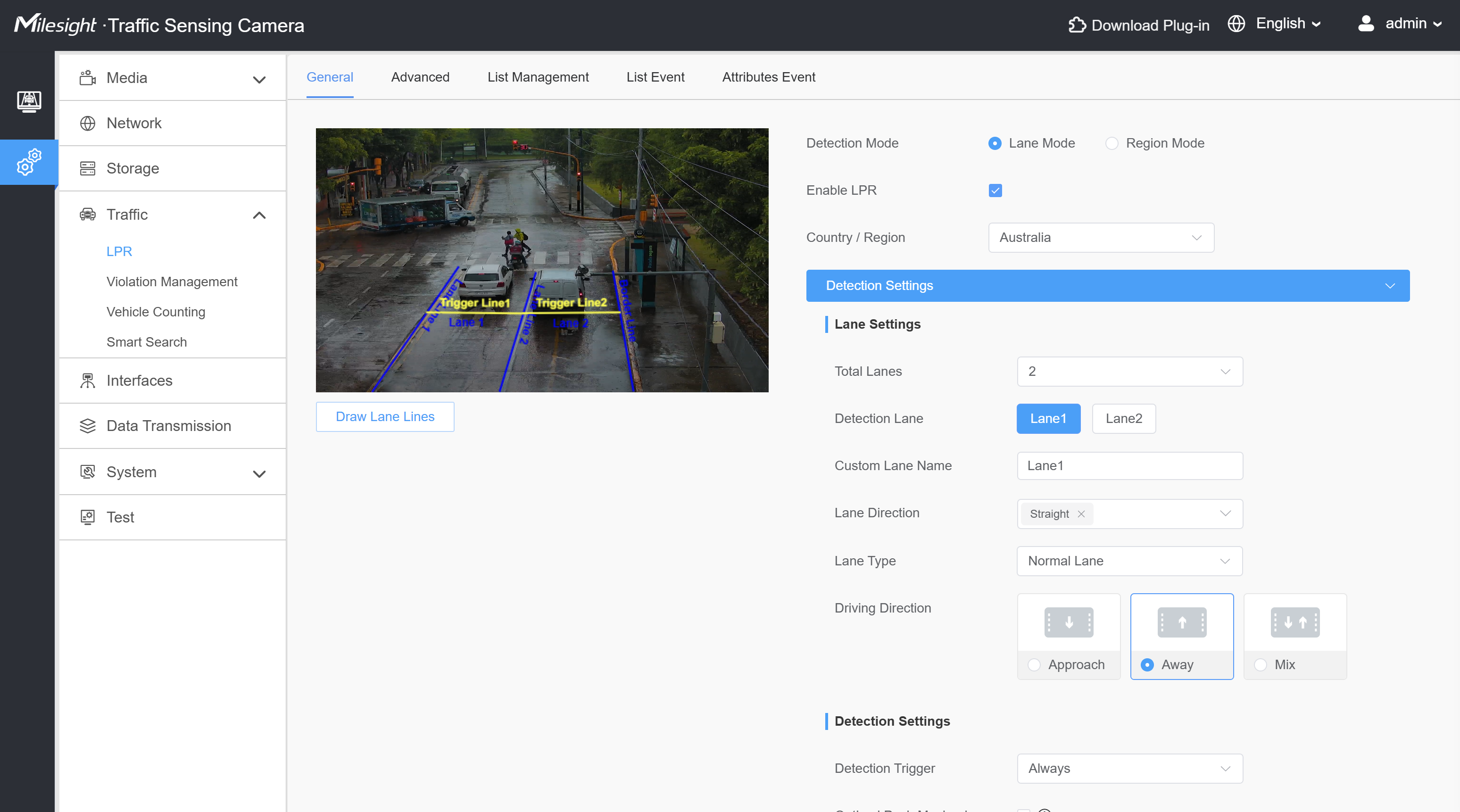
Figure 1 LPR lane mode
4. Obtaining the Traffic Light Status
Milesight TrafficX Enforcement camera (TS5511-GH) enables the detection of red-light violation events. To utilize this feature, the camera must first obtain the current status of the traffic lights. To achieve this, two possible traffic light signal docking methods have been implemented: External Input and Video Analysis.
Configuration when External Input is the signal docking mode:
1. Navigate to Settings – Traffic – Violation Management.
2. Under Detection Event you can find Signal Docking settings.
3. Select External Input as Docking Mode.
4. In the Lane Interface settings below, set Red Light Input No. for each detection line.
Information
Red Light Input No. and Yellow Light Input No. are used to configure external input interfaces for different colored lights (default is None).
|
|
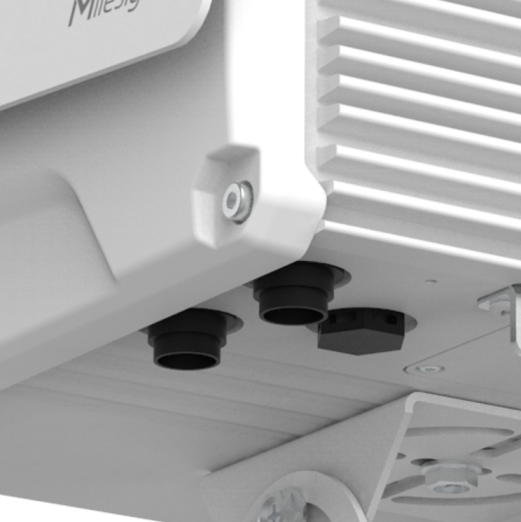
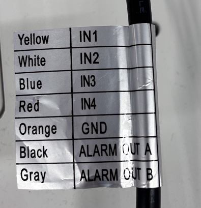
Figure 2 Connectors
These settings are linked to the External Input in the Basic Event section. If the corresponding input interface in Basic Event is set to High as the normal state, then Low will trigger an alarm. Note that detection is triggered only by the red-light state; the yellow-light state is not considered at this time.
For example, if the red-light signal for the through lane is configured to use Interface 1 in the high-level state, relevant detection will be enabled when Interface 1 transmits a high-level state.
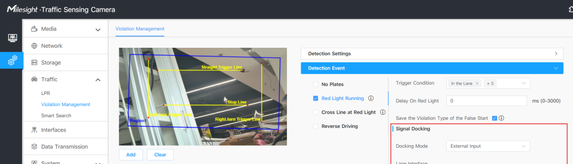
Figure 3 External Input
There’s another alternative when it is difficult to obtain the signals of the traffic lights in the way previously mentioned, you can also take advantage of the Video Analysis method.
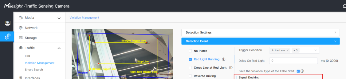
Figure 4 Video Analysis
Configuration when Video Analysis is the signal docking mode:
1. Navigate to Settings – Traffic – Violation Management.
2. Under Detection Event you can find Signal Docking settings.
3. Select Video Analysis as Docking Mode.
4. Click the Set button beside Area Settings to set the analyzed areas.
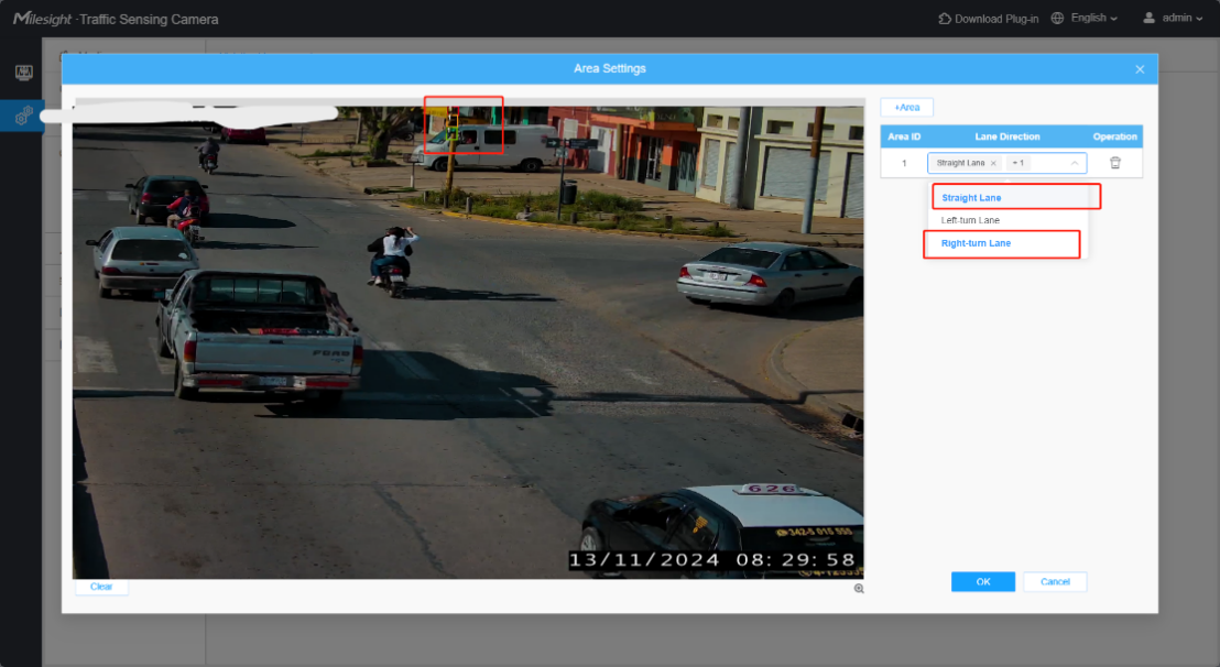
Figure 5 Area Settings
Information
"Area" refers to the zone where the traffic light is located; you must go to "Area settings" and click "+Area" to manually add and define it. A maximum of two Areas can be added—meaning up to two traffic lights can be monitored simultaneously—such as a straight-ahead signal combined with a left-turn or right-turn signal.
"Lane Direction" indicates the traffic direction controlled by the current signal (straight, left turn, or right turn); multiple directions can be selected simultaneously based on actual road conditions.
1. You can set the analyzed area for each detection line in the preview screen. Make sure that the traffic lights are encapsuled in the light detection boxes.
2. Click the OK button to save changes.
Configuration the traffic light detection function as needed
Traffic light fault detection is a new feature for the DualVision TrafficX Enforcement Camera(TS5511-GH); it promptly identifies traffic light anomalies and notifies operations and maintenance personnel, thereby ensuring the accuracy of traffic detection.
This function supports the detection of three fault states—"Light Up Simultaneously," "All lights off," and "Light Flashing"—and supports event data pushing and video recording.
Configuration method:
Go to Traffic > Violation Management > Traffic Light Status Detection > select a status (e.g., "All lights off").
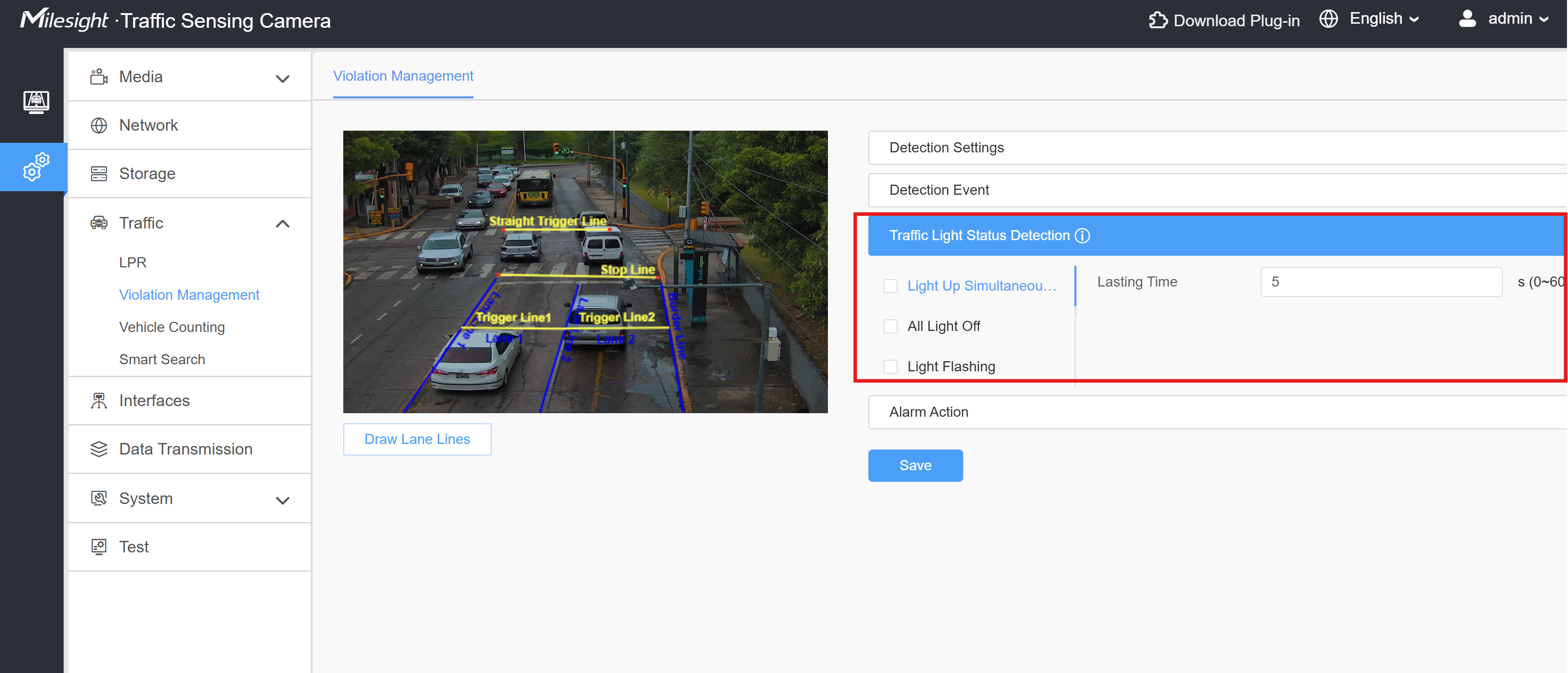
Figure 6 Traffic Light Status Detection
After configuring the event, if you need to save or send alarm data to the backend, must configure an alarm action.
Go to Traffic > Violation Management >Alarm action>select an action
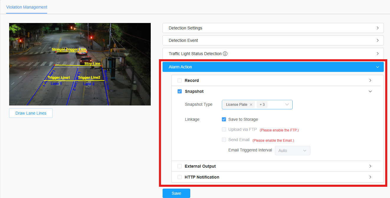
Figure 7 Alarm action
5. Configuration of Red-Light Violation Events
A standard traffic light intersection includes designated lanes for through traffic, left turns, and right turns. Consequently, four detection lines are required: a straight(through) lane detection line, a left turn detection line, a right turn detection line, and a stop line. These four trigger lines can be customized based on the specific requirements of the user.
Before enabling red-light violation detection or red-light crossing detection, ensure the detection area is properly configured, including the stop line and all relevant trigger lines.
Information
Given that red-light violation regulations vary across countries, the system provides open configuration options for event rules. Each configuration item is fully customizable to meet diverse requirements. It's important to note that the selected configuration determines the conditions for triggering an event.
For instance, if the user specifies both "Vehicle Front Crossed the Stop Line" and "Vehicle Tail Crossed the Stop Line" as conditions for a red-light violation event, the system will only generate a violation event when both conditions are met. At the same time, the phase capture logic will also adjust accordingly to align with the chosen configuration—capturing images strictly based on the selected criteria.
You can follow these steps to configure the red-light violation events:
1. Navigate to Settings – Traffic – Violation Management.
2. Configure the trigger lines and the detection regions. You can set up to 4 detection regions.
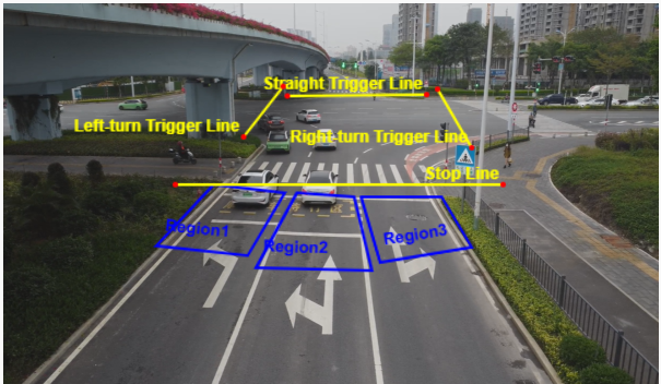
Figure 8 Detection Lines
3. Red-Light Running: In Detection Event section, select Red Light Running and configure the events.
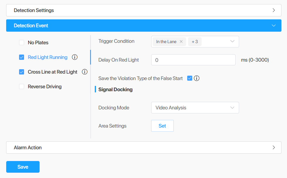
Figure 9 Red -Light Running
Information
Trigger Condition: Determines the conditions for an event to be triggered. All conditions should be satisfied at the same time. The conditions include In the Lane, Vehicle Front Crossed the Stop Line, Vehicle Tail Crossed the Stop Line and Reached Trigger Line.
Delay on Red Light: Refers to the delay time between when the traffic light turns red and when the system begins detecting violations. After the specified delay time has elapsed, the system starts detecting violations.
Save the Violation Type of the False Start: Whether to capture snapshots of false starts. A false start is when a driver starts the vehicle right before the traffic lights turn green but when the vehicle reaches the trigger lines, the traffic lights are already green.
1. Cross Line at Red Light: In Detection Event section, select Red Light Running and configure the events.
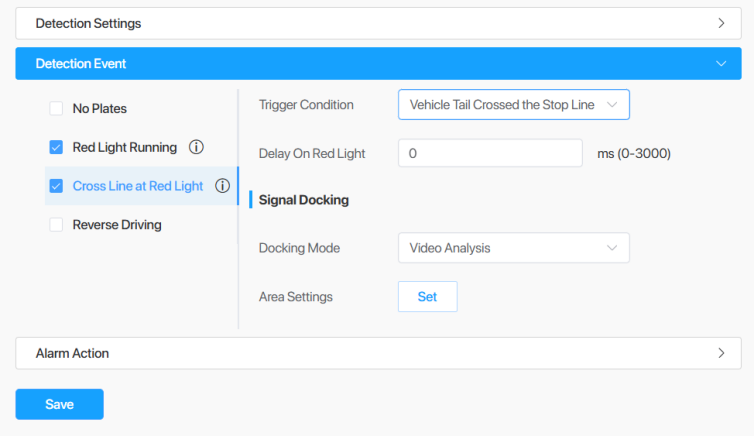
Figure 10 Cross Line at Red Light
2. In Alarm Action section, configured linked actions just like normal events.
3. After finishing the configurations, click the Save button to save changes.
Information
Cross Line at Red Light focuses specifically on detecting whether a vehicle crosses the stop line while the traffic signal is red. Red Light Running is a broader violation detection event that can use additional conditions, such as lane status, vehicle front/tail crossing the stop line, and reaching the trigger line, to determine whether the vehicle should be considered as running the red light.
If you still have questions about configuring the above functions, please refer to the configuration video at this link:
https://drive.google.com/file/d/1PjsQLfJ5u2aGw-2ODAvfYQprFKGyMJX-/view?usp=sharing
If you still encounter issues with red-light violation events on our TrafficX camera, please contact our support team at support@milesight.com.
—— END ——