
1.Introduction
This guide introduces the basic LAN connection methods for Milesight network cameras and the two common NVR installation topologies. Before access or commissioning, each camera must have an IP address compatible with the network to which it is connected.
2. Connect a Camera over the LAN
2.1 Connect a Camera Directly to a Computer
With a direct connection, the camera web page can be accessed only from the connected computer. The computer and camera must use compatible IP addresses.
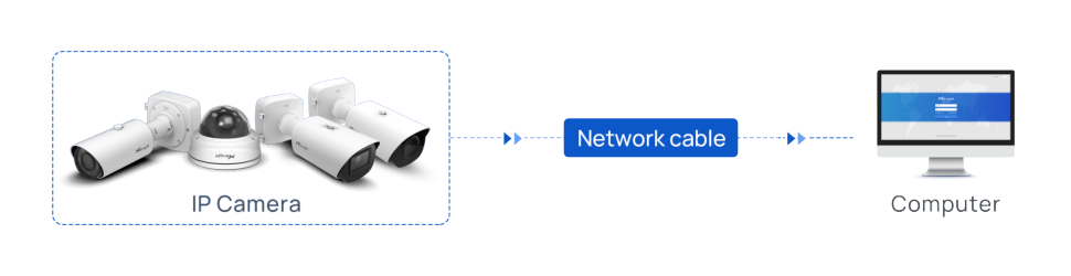
Figure 1. Connecting a camera directly to a computer
• Connect the camera and computer with a network cable.
• Provide the camera with the power supply required by the model. A standard computer Ethernet port does not provide PoE power.
• Set the computer and camera to the same IP subnet without creating an IP conflict.
Note: The default IP address of a Milesight network camera is 192.168.5.190. If the computer is on another subnet, temporarily assign the computer a compatible address before accessing the camera. |
2.2 Connect via a Switch or Router
Connect the network camera and the commissioning computer to the same switch or router. This method allows multiple devices on the LAN to communicate with the camera.
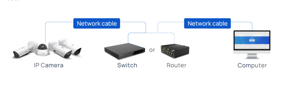
Figure 2. Connecting cameras through a switch or router
• When a PoE switch is used, a single Ethernet cable can carry both power and network data to a PoE camera.
• When a non-PoE switch or router is used, power the camera separately according to the product specification.
• Confirm that the camera, computer and NVR are on reachable network segments before adding the camera.
3. Select the NVR Connection Topology
3.1 Camera → PoE Switch → NVR
• Connect the IP cameras to the PoE switch for power and network transmission.
• Connect the PoE switch and NVR to the same LAN.
• Use this topology when the project requires flexible expansion, centralized switching or cameras distributed across the network.
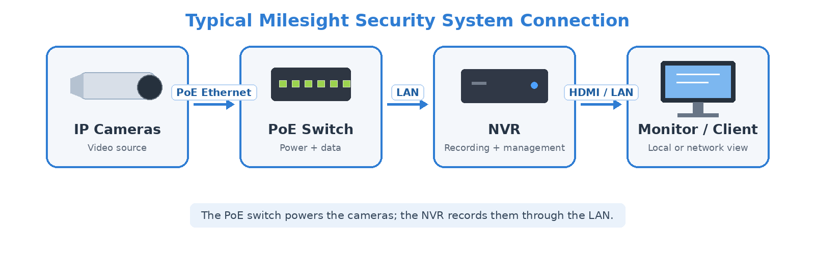
Figure 3. Cameras Connected to an NVR through a PoE Switch
3.2 Camera → PoE NVR
• Connect the camera directly to a PoE port on the NVR.
• The Ethernet cable carries both power and network data.
• Use this topology for small or straightforward installations where direct connection is preferred.
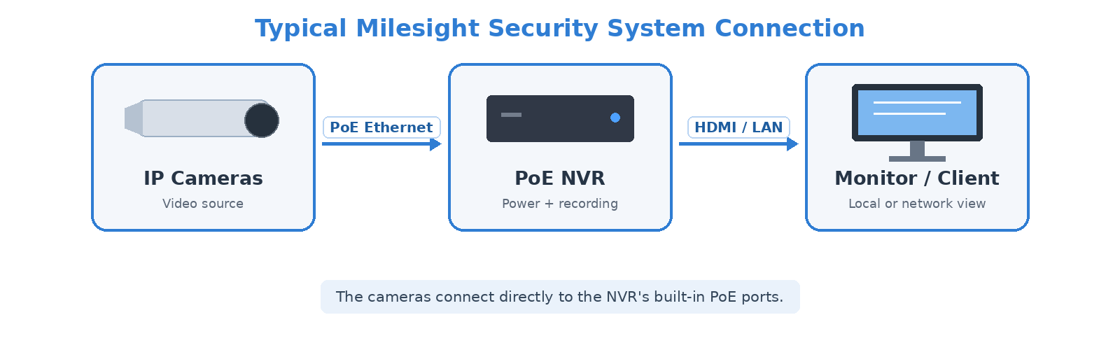
Figure 4. Cameras Connected Directly to a PoE NVR
4. Check the System Before Commissioning
Check Item | What to Confirm |
Power | The camera is powered on and the PoE/link status is normal. |
Network | The camera, NVR and commissioning computer can communicate on the intended LAN. |
IP Address | The IP address matches the project network plan and does not conflict with another device. |
Device Access | The camera web interface can be accessed before NVR integration. |
NVR Integration | Live view and recording are verified after the camera is added. |
Note: When troubleshooting, verify power, cabling, link status and IP reachability before checking application-layer settings. |
——————END——————