
1.Introduction
1.1Introduction of 5G AIoT Camera
Milesight 5G AIoT 4X/12X Pro Bullet Plus Network Camera is our newest member of the 5G series. Featuring cutting-edge 5G technology, the 5G AIoT Pro Bullet Plus Network Camera provides a fresh experience of UHD image quality, low latency, and fast transmission speed in some scenarios where network wiring is inconvenient. Offering IoT technology, AI deep learning, compact structure and more, Milesight 5G AIoT Pro Bullet Plus Network Camera builds a whole new world by combining high-tech with high performance. IoT is an advanced function that allows us to get information on any things that need to be monitored, connected, and interacted with in real-time via various technologies and devices, like sensors and RFID to smartly realize perceiving, recognizing, and managing things.
This article will introduce the basic configuration of the 5G AIoT camera so that you can quickly learn to use our 5G AIoT camera.
1.2Model
• Milesight 5G AIoT 4X/12X Pro Bullet Plus Network Camera
• Milesight 5G AI 4X/12X Pro Bullet Plus Network Camera
• Milesight 5G AI Motorized Pro Bullet Plus Network Camera
2.How to Set IoT
2.1 Device Setting
Step 1: After logging into the web, go to “IoT“→ “Settings“→ “Radios Settings“. Check the checkbox “Enable IoT” and IoT function will be enabled automatically without clicking the save button.
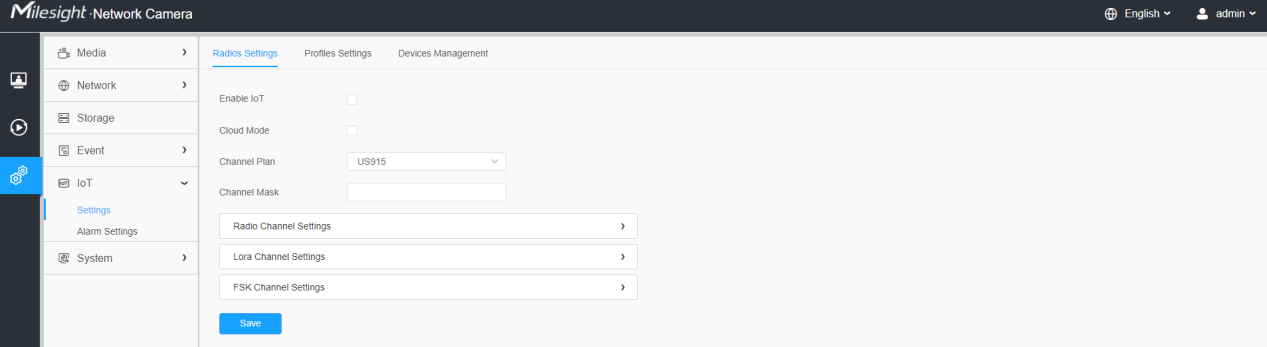
Please refer to the meaning of the options as follows:
Parameters | Function Introduction |
Enable IoT | Enable/ disable the IoT function. |
Cloud Mode | Enable/ disable Milesight IoT Cloud management. |
Channel Plan | Show the corresponding channel plan of your IoT camera. |
Channel Mask | Enabled frequencies are controlled using channel mask. Leave it blank means using all the default standard usable channels specified in the LoRaWAN® regional parameters document. A bit in the Channel Mask field set to 1 means that the corresponding channel can be used for uplink transmissions if this channel allows the data rate currently used by the end-device. A bit set to 0 means the corresponding channels should be avoided.This option is optional for CN470, US915 and AU915. |
Step 2: Configure Radios Settings.
Currently our IoT camera supports three IoT frequency bands of 915M (The corresponding channel plan is US915/AU915/KR920/AS923/AS923-2), 868M (The corresponding channel plan is IN865/EU868/
RU864) and 470M (The corresponding channel plan is CN470). Before buying the camera, you need to contact our sales to choose the frequency band that is supported in your country.
For example, here I choose the IoT camera with the frequency bands of 915M or reference document regional parameters for LoRaWAN, and it will show that the current channel plan is US915 on the camera’s web.
Note: Usually you can directly use the default settings without configuring Radio Settings. If you need to customize some radio settings, you can make further settings as shown below.
[Radio Channel Settings]
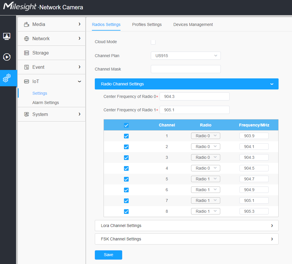
Please refer to the meaning of the options as follows:
Parameters | Function Introduction |
Center Frequency of Radio 0 | Supports transmitting and receiving packet; Note: For details of default value and configuration ranges in different regions, please refer to Appendix 1 at the end of this document. |
Center Frequency of Radio 1 | Only supports receiving packet from nodes; Note: For details of default value and configuration ranges in different regions, please refer to Appendix 2 at the end of this document. |
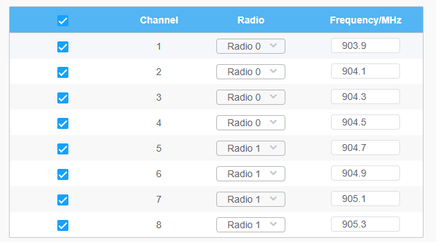
Multi-channel list | The radio and frequency corresponding to all channels will be listed here. All channels are enabled by default. You can also check the box to enable the corresponding channel.
|
[Lora Channel Settings]
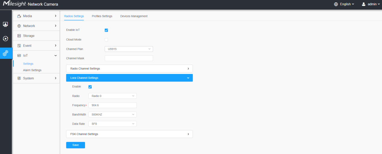
Please refer to the meaning of the options as follows:
Parameters | Function Introduction |
Enable | Enable/ disable the LoRa Channel. |
Radio | Choose Radio 0 or Radio 1 as center frequency. |
Frequency | Enter the frequency of this channel. For example: • The frequency range formula of US915 and AU915: Center frequency ±0.55; • The frequency range formula of other regions (except US915 and AU915): Center frequency ±0.4625; For example, the center frequency is configured with 867.5, then the frequency range corresponding to each channel: 867.5-0.4625~867.5+0.4625. |
BandWidth | Enter the bandwidth of this channel. 125KHz, 250KHz and 500KHz are available. The default option is 250KHz; Note: The default option is 500KHz for AU915 and US915. |
Data Rate | From SF7 to SF12, the transmission rate decreases and the transmission distance increases. In general, the range of Data Rate is SF7 ~ SF12, the default value would be SF7. Only the default value of the Channel Plan AU915 and US915 is SF8. |
[FSK Channel Settings]
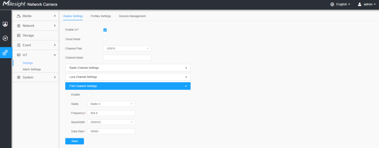
Please refer to the meaning of the options as follows:
Parameters | Function Introduction |
Enable | Enable/ disable the FSK Channel. |
Radio | Choose Radio 0 or Radio 1 as center frequency. |
Frequency | Enter the frequency of this channel. |
BandWidth | Enter the bandwidth of this channel. 125KHz, 250KHz and 500KHz are available. The default option is 125KHz; Note: The default option is 250KHz for AU915 and US915. |
Data Rate | Enter the data rate. The Date Rate must be between 500~250000. |
Note:
The configurations here should be the same with those in End Device.
Step 3: Configure Profiles Settings.
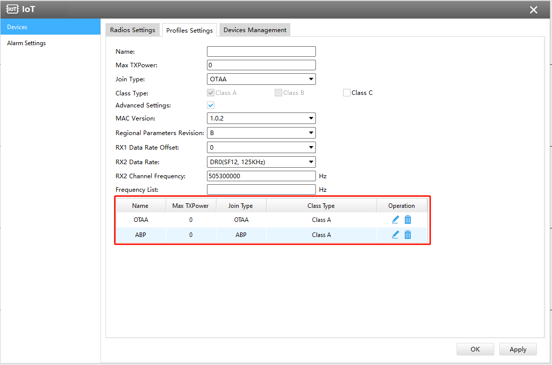
Usually you can use the default settings without configuring Profiles Settings. If you need to customize some profiles settings, you can click the Profiles Settings button to make further settings and click Apply button, it will list the Device-profiles you created.
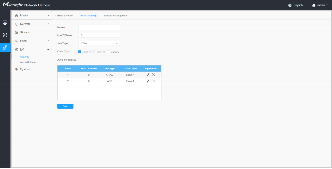
Please refer to the meaning of the options as follows:
Parameters | Function Introduction | |
Name | Customize the profile name. | |
Max TXPower | Enter the maximum transmit power. The TXPower indicates power levels relative to the Max EIRP level of the end-device. 0 means using the max EIRP. EIRP refers to the Equivalent Isotropically Radiated Power. The Max TXPower must be between 0~16. | |
Join Type | OTAA and ABP are optional, the default option is OTAA. • OTAA: Over-the-Air Activation. For over-the-air activation, end-devices must follow a join procedure prior to participating in data exchanges with the network server. An end-device has to go through a new join procedure every time as it has lost the session context information. • ABP: Activation by Personalization. Under certain circumstances, end-devices can activate by personalization. Activation by personalization directly ties an end-device to a specific network by passing the join request - join accept procedure. | |
Class Type | Device type is Class A by default. Users can check the box of Class B or Class C to add the class type. | |
Advance Settings | MAC Version | Choose the version of the LoRaWAN® supported by the end-device. 1.0.0/1.0.1/1.0.2/1.1.0 are optional, the default option is 1.0.2. |
Regional Parameters Revision | Revision of the Regional Parameters document is supported by the end-device.A and B are optional, the default option is B. | |
RX1 Data Rate Offset | The offset used for calculating the RX1 data-rate is based on the uplink data-rate. | |
RX2 Data Rate | Enter the RX2 data rate which is used for the RX2 receive-window. | |
RX2 Channel Frequency | RX2 channel frequency is used for the RX2 Frequency receive-window. | |
Frequency List | List of factory-preset frequencies. The range is based on what is specified in the LoRaWAN® regional parameters document. | |
Step 4: Add and manage End Devices.
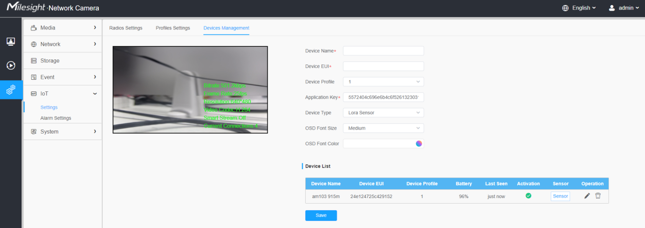
The camera web interface when select OTAA as Join Type of Device Profile
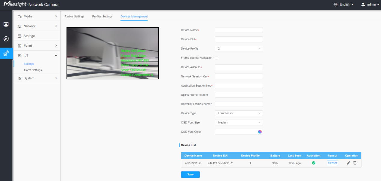
The camera web interface when select ABP as Join Type of Device Profile
Please refer to the meaning of the options as follows:
Parameters | Function Introduction |
Device Name | Customize the device name. |
Device EUI | Fill in Device EUI which can be obtained from the device label. You can also get Device EUI from Milesight Tool Box if you use Milesight Lora Sensor. |
Device Profile | Select the device profile you configured before. Refer to step 3 for more details about how to configure it. |
Frame-counter Validation | If disable the frame-counter validation, it will compromise security as it enables people to perform replay-attacks. This function can be used to judge whether the package loss occurs. |
Application key | Whenever an end-device joins a network via over-the-air activation, the application key is used for derive the Application Session key. It is mainly used to generate corresponding Device Address/Network Session Key/Application Session Key. Note: • The default key can be obtained from the end-device. • Milesight Sensors’ default key is 5572404c696e6b4c6f52613230313823. |
Device Address/Network Session Key/Application Session Key | Information needed to access the network. If you choose ABP network access mode, you need to fill in these items. And you can obtain them from End Device. For example, you can get such information from Milesight Tool Box when you use Milesight Lora Sensor. Device Address: The device address identifies the end-device within the current network. Network Session Key: The network session key is specific for the end-device. It is used by the end-device to calculate the MIC or part of the MIC (message integrity code) of all uplink data messages to ensure data integrity. The default key of Milesight Sensor is 5572404c696e6b4c6f52613230313823. Application Session Key: The AppSKey is an application session key specific for the end-device. It is used by both the application server and the end-device to encrypt and decrypt the payload field of application-specific data messages. The default key of Milesight Sensor is 5572404c696e6b4c6f52613230313823. |
Uplink Frame-counter | Calculate the number of uplink frames sent from End Device to network server. This count is increased and received by the End Device. The default value is 0. |
Downlink Frame-counter | The number of data frames which sent uplink to the network server. It will be incremented by the end-device and received by the end-device. Users can reset the personalized end-device manually, then the frame counters on the end-device and the frame counters on the network server for that end-device will be reset to 0. The default value is 0. |
Device Type | Select the device type according to the actual situation. Lora Sensor and Lora Sensor Node are optional. Lora Sensor is a kind of sensor that supports LoraWAN protocol, while Lora Sensor Node is a kind of device which receives data from interfaces of RS485, AI and GPIO. |
OSD Font Size | Configure the OSD font size. |
OSD Font Color | Configure the OSD font color. |
Note:
①Device Name and Device EUI cannot be repeated.
②Device EUI, Application Key, Device Address, Network Session Key and Application Session Key should be consistent with the configuration of End Device.
③Uplink Frame-counter and Downlink Frame-counter can be reset only in ABP mode.
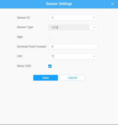
Step 5: Sensor Settings. You can enter sensor configuration page by clicking “Sensor”。After the configuration is finished, you can click “Save" to save your configuration or click "Cancel"to cancel your configuration.

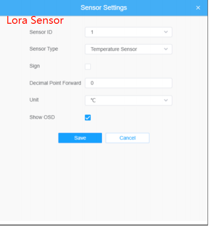
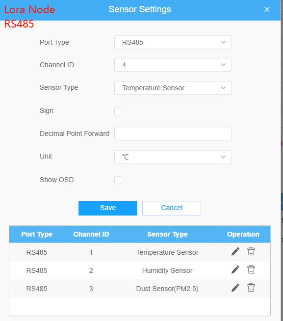
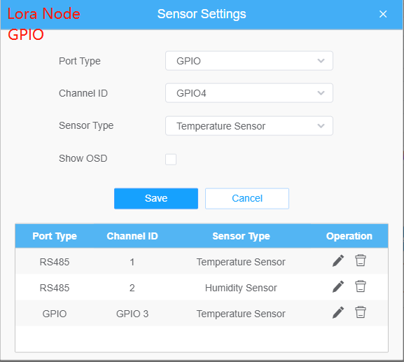
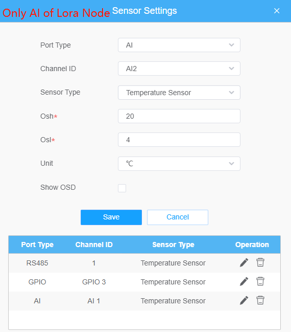
Please refer to the meaning of the options as follows:
Parameters | Function Introduction | ||
Sensor ID | Select the Sensor ID that you want to configure. The number of sensor IDs depends on how many kinds of data the sensor has and there is a one-to-one relationship between ID and data. | ||
Port Type | Select the correct port type according to the actual situation. RS485, GPIO and AI are available. Note: Only for LoRa Node; | ||
Channel ID | Select the Channel ID that you want to configure. There are eight Channel IDs for each kind of interface. | ||
Osh | The high value of the device range. Note: Only AI of LoRa Node; | ||
Osl | The low value of the device range. Note: Only AI of LoRa Node; | ||
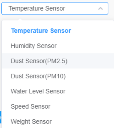
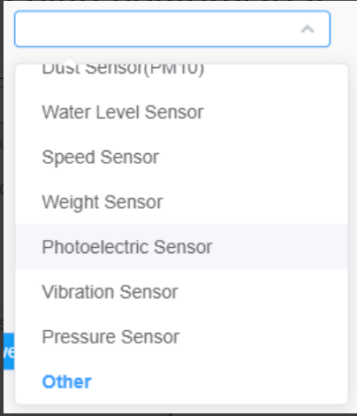
Sensor Type | Sensor Type configuration. We have several common used sensor types as shown below:
Or you can also customize it:
| ||
Sign | The tick indicates that the value has a plus or minus sign. | ||
Decimal Point Forward | Decimal configuration. For example, when you fill in 1, you are moving the decimal point one to left, and you get a decimal. | ||
Unit | Data unit configuration. We have some common units here and users can also customize it. | ||
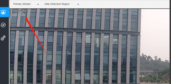
Show OSD | As the picture shown below, once you enable this function, you can see the detected data on the screen.
|
Note:
①The channel ID and Sign should be consistent with those in End Device.
②Decimal Point Forward is set according to the properties of the sensor. For example, you need to set this value to 1 to get the correct temperature when using the Milesight temperature sensor.
Step 6: You can click this button to modify the configuration in Device Management.
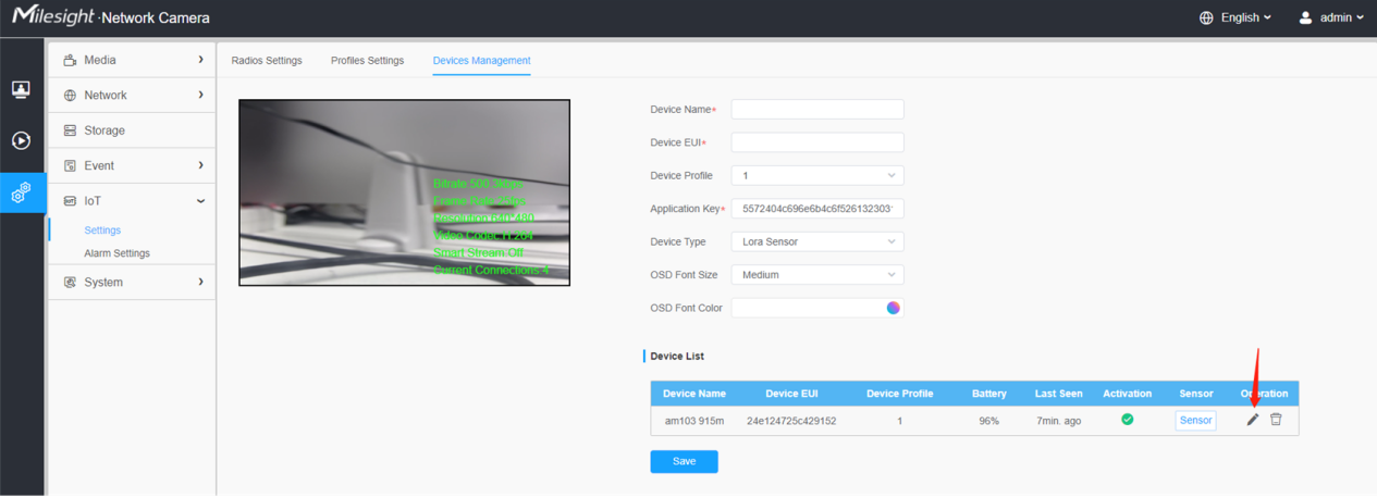
Step 7: You can click this button to delete the device you added.

Note:
①About how to add IOT sensor, here we share videos for you:
https://drive.google.com/file/d/1T0mQxhwtoN4Psj2DFz0cVJ-nDnthEVV7/view
https://www.youtube.com/watch?v=wgkDZMv17Gs
Please noted that after adding sensor in the camera web page, you need use the ToolBox to add and restart the sensor, make it can receive data normally. And if you can not get correct value from the sensor, please try to reset the sensor in ToolBox and test again.
Here you can download the ToolBox:
https://www.milesight.com/iot/resources/download-center/#software-platform
②The sensor models that support IOT are as follows:
• AM107
• AM104
• AM307
• AM319
• EM300-TH
• EM300-MCS
• EM300-SLD
• EM300-ZLD
• EM500-Co2
• EM500-SMTC
• EM500-SMT
• EM500-UDL
• EM500-SWL
• EM500-PP
• EM500-LGT
• EM500-PT100
• EM500-SWL
2.2 Alarm Settings
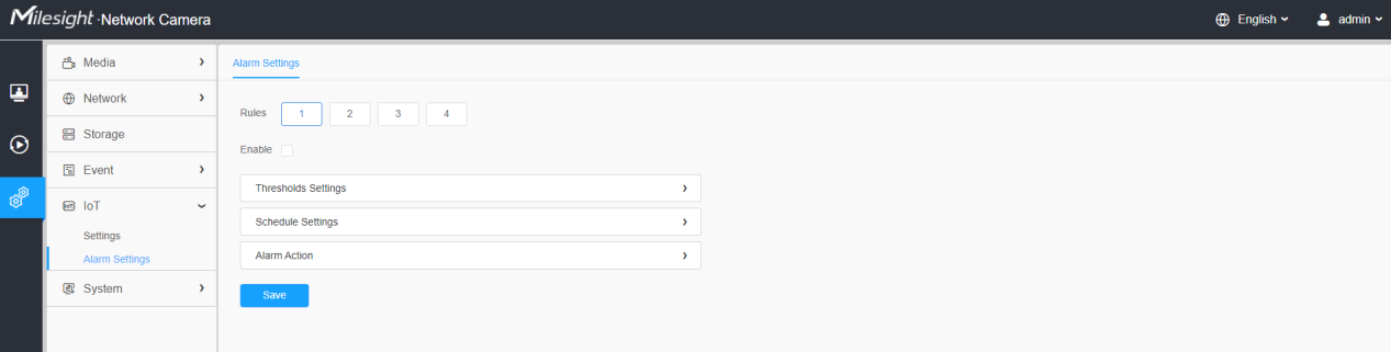
Step 1: Select the alarm rule that you want to set and you can configure four kinds of rules.
Step 2: Check the checkbox to enable Alarm Rules.
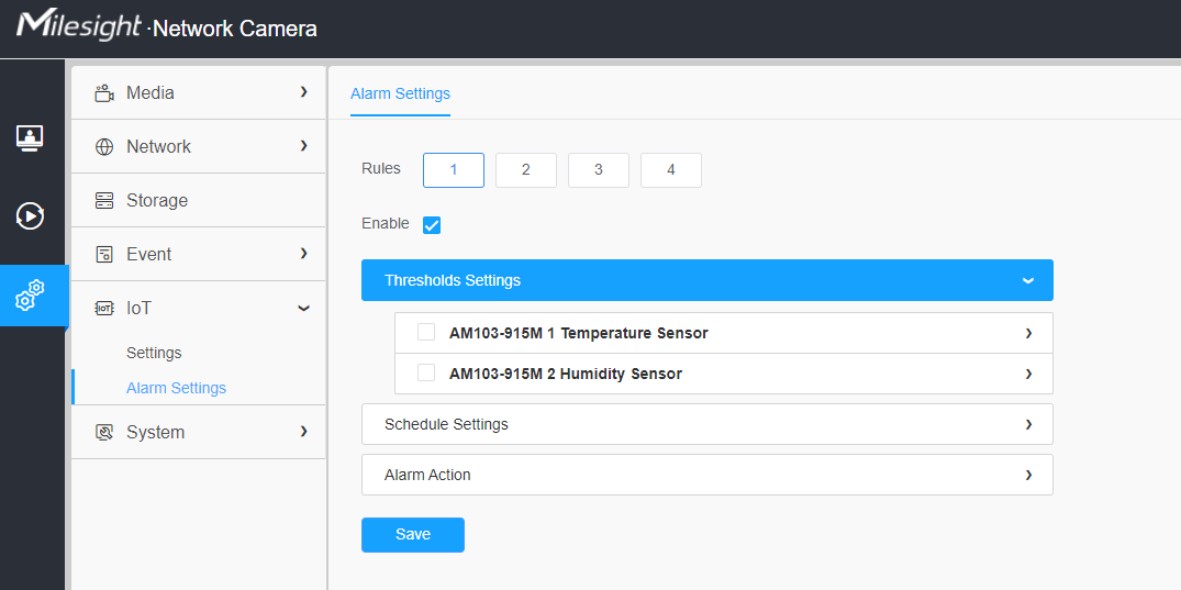
Step 3: Click to select the sensor to alarm.
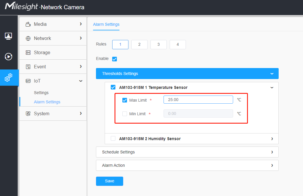
Step 4: Set threshold for the selected sensor.
When the data reaches the critical value, the alarms will be triggered. Both upper and lower thresholds are configurable. You can also only configure upper or lower threshold.
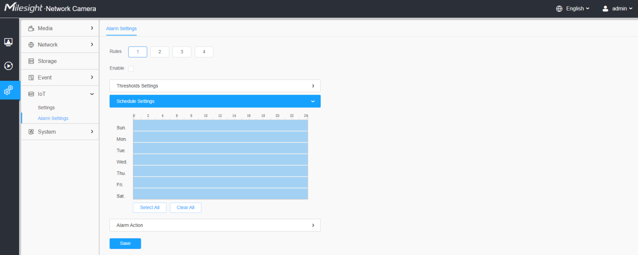
Step 5: Set the alarm schedule for IoT.
Step 6: Set Alarm Action.
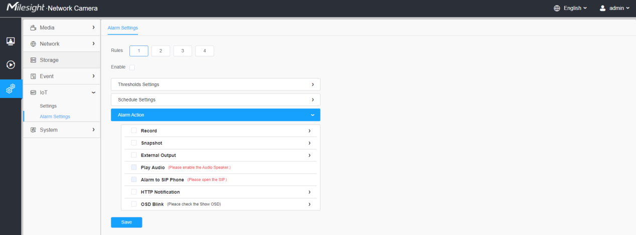
Please refer to the meaning of the options as follows:
Parameters | Function Introduction |
Record | Duration: Selected the duration time of alarm. 5s/10s/15s/20s/25s/30s are available. Linkage: Save alarm recording files into SD Card or NAS or Upload the recording files via FTP. |
Snapshot | Number: The number of snapshot, 1~5 are available. Interval: This cannot be edited unless you choose more than 1 to Snapshot. Linkage: Save alarm recording files into SD Card or NAS, Upload the recording files via FTP and send alarm email. |
External Output | If the camera equips with External Output, you can enable the action after configuring the trigger duration. |
Play Audio | Auto/10 seconds/30 seconds/1 minute/5 minutes/10 minutes are available. Note: Please enable the Audio Speaker. |
Alarm to SIP Phone | Support to call the SIP phone after enabling the SIP function. Note: Please open the SIP. |
HTTP Notification | Support to pop up the alarm news to specified HTTP URL. |
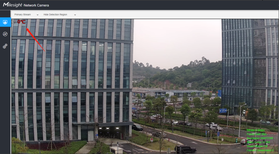
OSD Blink | If the Show OSD in the page of sensor configuration is checked, the OSD will blink when alarm is triggered. OSD Blink Time: Support to set the blinking duration of the OSD, 1~10 are Available. For example, the alarm action is set to OSD blinking at an interval of 3 seconds, when the data reaches the critical value, the alarms will be triggered and the OSD blinking on the live view interface.
|
3.How to Configure 5G Camera
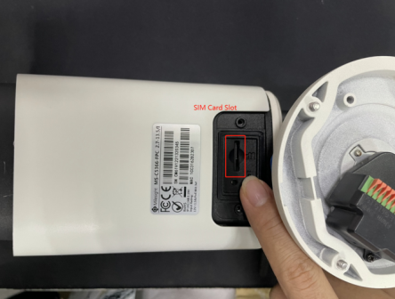
Step 1: Insert the SIM card into the SIM card slot at the bottom of the camera, as shown below:
Here is video about how to insert the SIM card:
https://drive.google.com/file/d/1pTxagjR_f_6fYLTU1PGO51er_Yxbqath/view?usp=sharing
Note:
①It supports Nano SIM for SIM card slot.
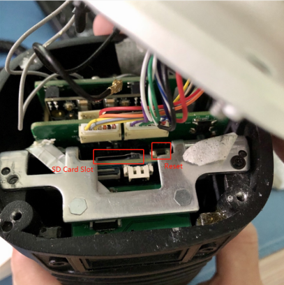
②For 5G camera, the SD card slot is inside the camera, as shown below:
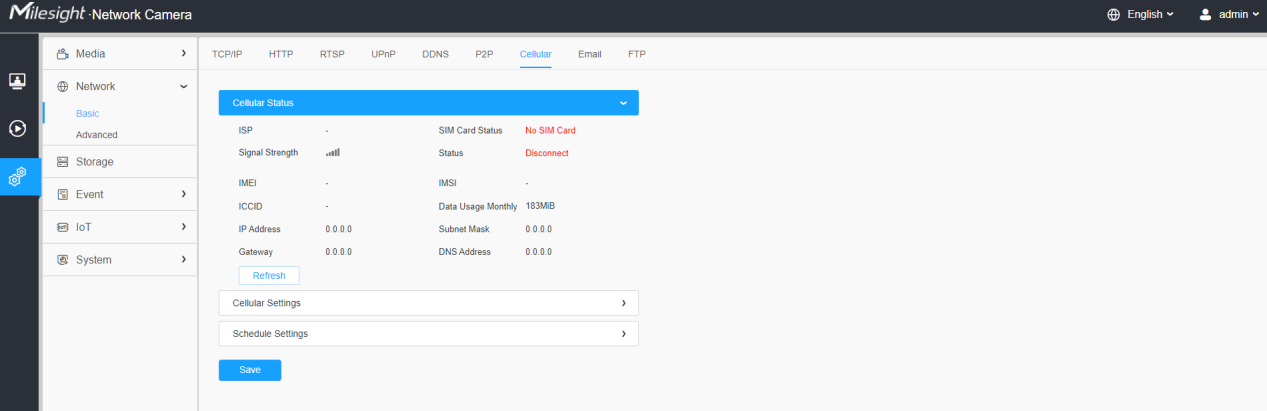
Step 2: After logging into the web, go to “Network“→ “Basic“→“Cellular“, you can check the cellular
status and set the cellular settings here, as shown below.
Note:
①If you use the 5G camera for the first time, it is necessary to connect the camera through
the network port to access the webpage of the camera for basic configuration.
②If the SIM Card Status shows "No SIM Card," this is generally because the camera is unable to detect the SIM card. It is recommended to reinsert the SIM card until it displays "connected" or "invalid" to indicate successful insertion.
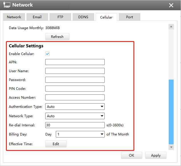
Step3: Fill in the information provided by your Internet Service Provider (ISP) to Cellular Settings interface, then click Save to access the network successfully.
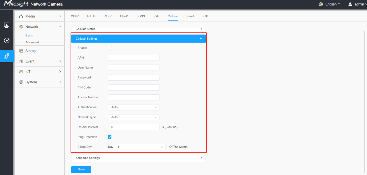
Please refer to the meaning of the options as follows:
Parameters | Function Introduction |
Enable | Check this option to enable 5G network. |
APN | Enter the Access Point Name for cellular dial-up connection provided by local ISP. |
Username | Enter the username for cellular dial-up connection provided by local ISP. |
Password | Enter the password for cellular dial-up connection provided by local ISP. |
PIN Code | Enter a 4-8 characters PIN code to unlock the SIM. |
Access Number | Enter the dial-up center NO. For cellular dial-up connection provided by local ISP. |
Authentication Type | Select the Authentication Type. There are five options including Auto, PAP, CHAP, MS-CHAP, MS-CHAPv2 to match different Internet Service Providers. The default option is Auto, which can automatically match Internet Service Provider. |
Network Type | Select the network type of cellular network. There are five options including Auto, 5G, 4G, 3G and 2G. Auto: connect to the network with the strongest signal automatically. |
Re-dial Interval | Fill in the re-dial interval time. When the 5G network is offline, it will re-dial according to the interval you set. The Re-dial Interval must be between 0-3600s. |
Ping Detection | Enable it to make camera ping external network(8.8.8.8/114.114.114.114) at regular intervals, ensure the 5G modules is running normally. If ping failed, the 5G module will restart. |
Billing Day | Select the date for clearing the data each month. Users can choose from 1st to 31st, and the system will clear the data on the date you set each month. |
Note:
①For some Internet Service Provider, users only need to insert the SIM card directly to
access the 5G network without additional configuration.
②As long as the SIM card is inserted and cellular is enabled, it will consume the data of the SIM card. If there is live video streaming, it will consume more data.
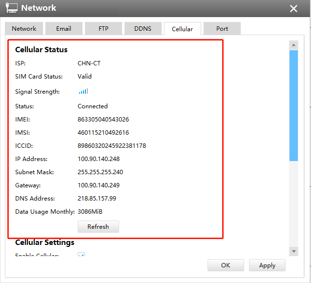
Step4: After connecting to the network successfully, you can check the cellular status
information on Cellular Status interface, as shown below.
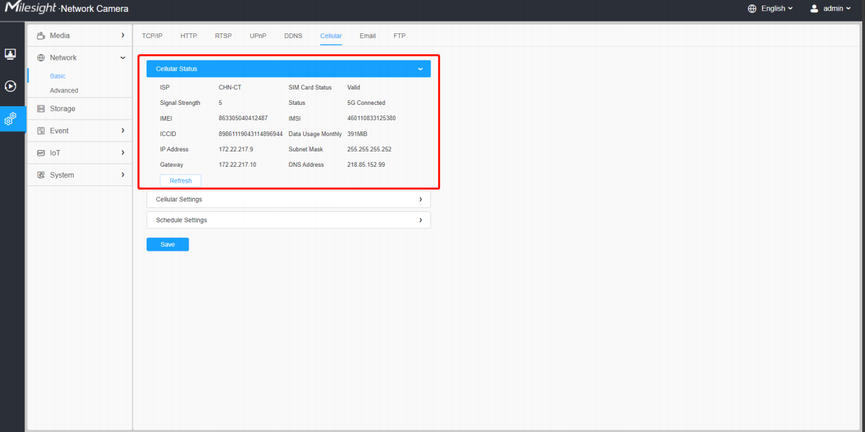
Please refer to the meaning of the options as follows:
Parameters | Function Introduction |
ISP | Show the network provider which the SIM card registers on. Note: It will display "-" when the SIM card is not inserted or not recognized. |
SIM Card Status | Display the connection status of SIM card. No SIM Card: The SIM card is not inserted. Invalid: The SIM card has been inserted but failed to connect to the network. Valid: The SIM card has been inserted and successfully connected to the network. |
Signal Strength | Display the current signal strength of the network. |
Status | Display the connection status of the network, including “connect” and “disconnect”. |
IMEI | Show the IMEI of the module. |
IMSI | Show IMSI of the SIM card. |
ICCID | Show ICCID of the SIM card. |
Data Usage Monthly | Display current monthly used data. |
IP Address | Display the IP Address, Subnet Mask, Gateway and DNS Address of the current network. If the SIM card is not inserted or not recognized, it will display 0.0.0.0. |
Subnet Mask | |
Gateway | |
DNS Address |
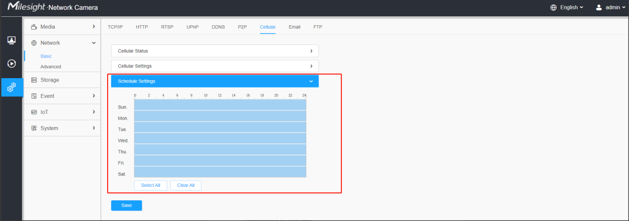
Step 5: Set the schedule, the 5G network will take effect according to the schedule you set.
Step 6: After configuring the cellular settings, you also need to complete other basic configurations of the camera if needed, such as events, recordings, etc.
Step 7: After completing the basic settings of the camera, you can access the camera using 5G network without connecting the network cable.
Note:
• You can connect and configure the 5G camera to Milesight CMS via P2P.
• You can use 5G network to connect the 5G camera to Milesight VMS Enterprise, Milesight
CMS and M-sight Pro APP via P2P.
4.Compatibility between 5G AIoT Camera and Milesight Back-end
After completing the basic settings of 5G AIoT camera, you can access the camera through the Milesight back-end using 5G network without connecting the network cable.
• For Milesight CMS, it supports adding 5G camera via P2P using 5G network, and then the parameter of 5G and IoT can be configured.
|
|
5G Settings
|
|
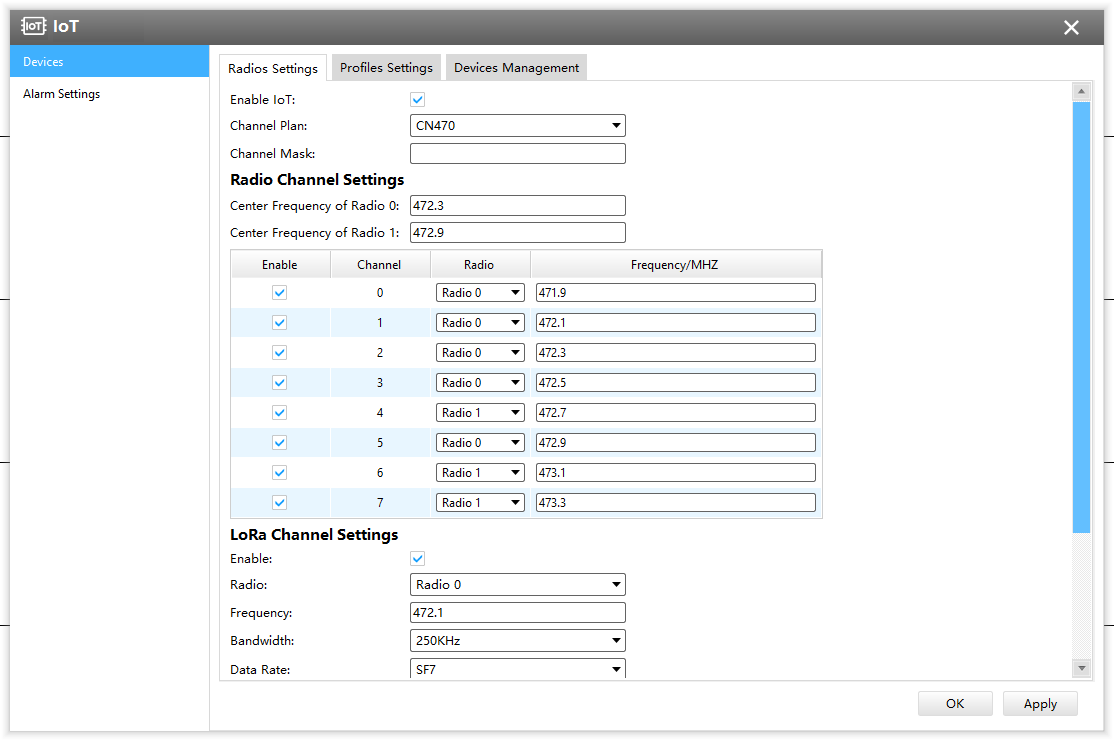
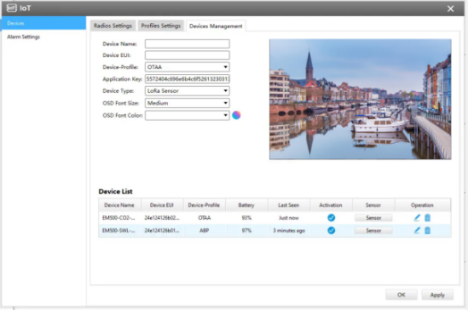
IoT Settings
• For Milesight VMS Enterprise, it supports adding 5G camera via P2P using 5G network.
• For M-sight Pro APP, it supports adding 5G camera via P2P using 5G network.
• For Milesight IoT Cloud, it supports adding IoT Camera to Milesight IoT Cloud as a gateway, and then manages the sensor data on the cloud centrally.
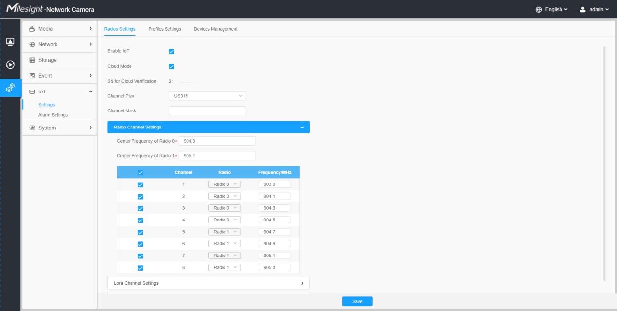
Interface of IoT Camera
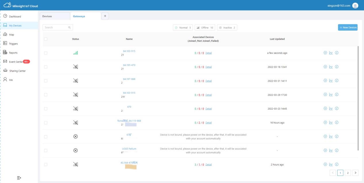
Interface of Milesight IoT Cloud
Note:
①For a 5G camera, the P2P function will be activated by default as shown below.
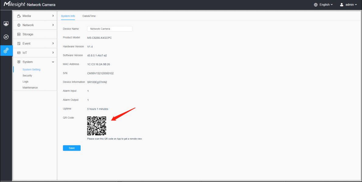
②If you don’t need to use the 5G network, you can connect to the camera through a network cable to use it.
—— END ——
Appendix 1
According to different regions, the default value and configurable range of the Center Frequency of Radio 0 are different, as follows:
Channel Plan | Default Value | Configurable Range |
EU868 | 867.5 | 863-870 |
IN865 | 865.3 | 865~867 |
RU864 | 868.9 | 864~870 |
US915 | 904.3 | 902~928 |
AU915 | 917 | 915~928 |
AS923 | 923 | 915~928 |
AS923-2 | 921.5 | 915~928 |
KR920 | 922.3 | 920.9~923.3 |
CN470 | 472.3 | 470~510 |
Appendix 2
According to different regions, the default value and configurable range of the Center Frequency of Radio 1 are different, as follows:
Channel Plan | Default Value | Configurable Range |
EU868 | 868.5 | 863~870 |
IN865 | 866.385 | 865~867 |
RU864 | 867.7 | 864~870 |
US915 | 905.1 | 902~928 |
AU915 | 917.8 | 915~928 |
AS923 | 922.2 | 915~928 |
AS923-2 | 922.3 | 915~928 |
KR920 | 923.1 | 920.9~923.3 |
CN470 | 472.9 | 470~510 |